Part 3 – Exciters
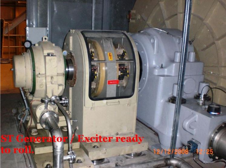
Exciters
Video: Exciter
Watch “Exciter” [0:41].
The power source excites the field windings of a synchronous generator, inducing AC voltage and current in the armature. The amount of excitation required to maintain the output voltage constant is a function of the generator load. As the generator load increases, the amount of excitation increases.
- Lagging PF loads require more excitation than unity PF loads
- Leading PF loads require less excitation than unity PF loads
There are two basic kinds of exciters:
- Rotating: brush and brushless
- Static exciters: shunt and series
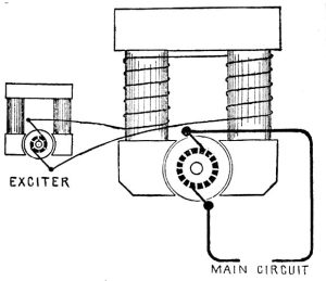
Exciters provide DC to the alternator’s field windings for pole magnetization. The exciter’s voltage is regulated by a voltage regulator and can be supplied through self-excitation or separate excitation methods to the main field.
Self-Excitation
A small DC generator with permanent magnets on the main rotor shaft utilizes residual magnetism to generate initial voltage and current. This output is then fed to the main rotor winding of the AC generator.
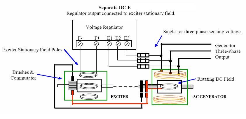
Separate Excitation
In large power-generating stations with multiple alternators running in parallel, a separate DC supply bus is employed. This serves as a protective measure to ensure that in the event of one alternator failing, the remaining alternators can continue to utilize the DC bus for excitation.
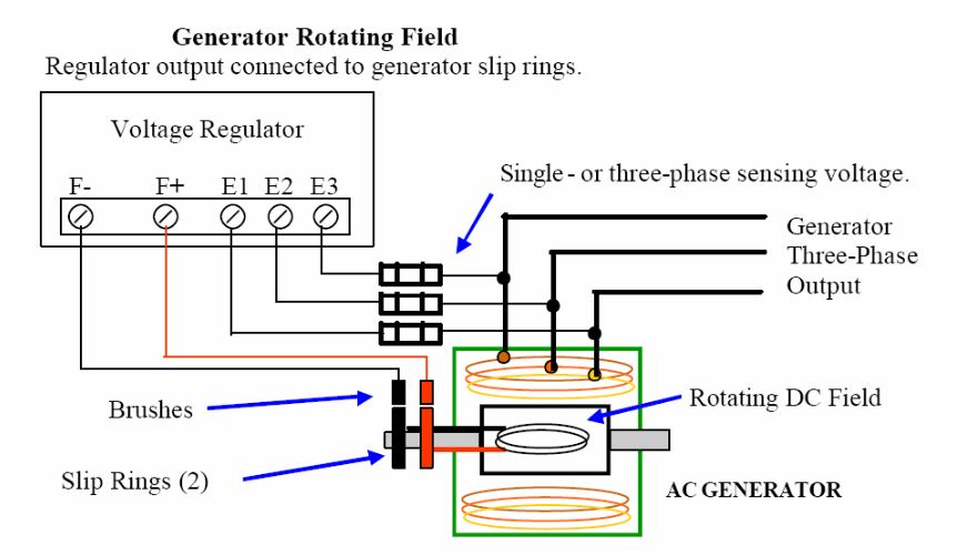
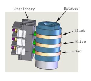
DC excitation voltage is delivered to the main rotor’s field through brushes and slip rings, which are commonly referred to as collector rings. The current and voltage demands of these slip rings and brushes are relatively minor when contrasted with the voltage and current output (KVA) of the main stator.
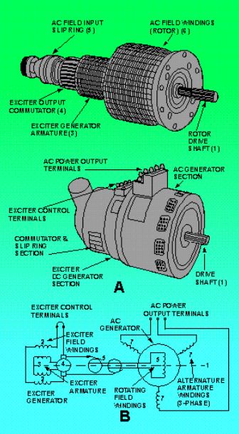
Brushless Exciter
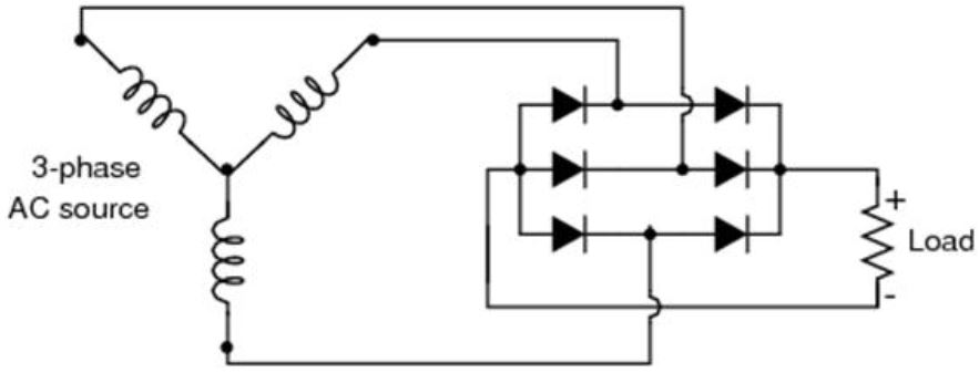
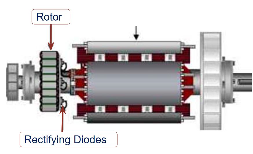
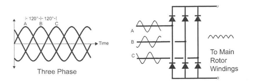
A small AC generator is installed on the main shaft, and the AC voltage it produces is rectified into DC by a 3-phase rotating rectifier assembly on the same shaft. This DC voltage is then directed to the main generator field, with a voltage regulator in place to manage the exciter field current.
Activity: Brushless Exciter
Click the arrows to see images of brushless exciters.
The use of a brushless exciter eliminates the requirement for collector rings and brushes, reducing maintenance needs. This system allows for precise control of the field voltage, ensuring a stable and well-regulated generator output voltage. As a result, nearly all modern synchronous generators employ this brushless exciter technology.
Modern Excitation Methods
Modern exciters use solid-state devices such as diodes, silicon-controlled rectifiers (SCRs), or thyristors to rectify the voltage.
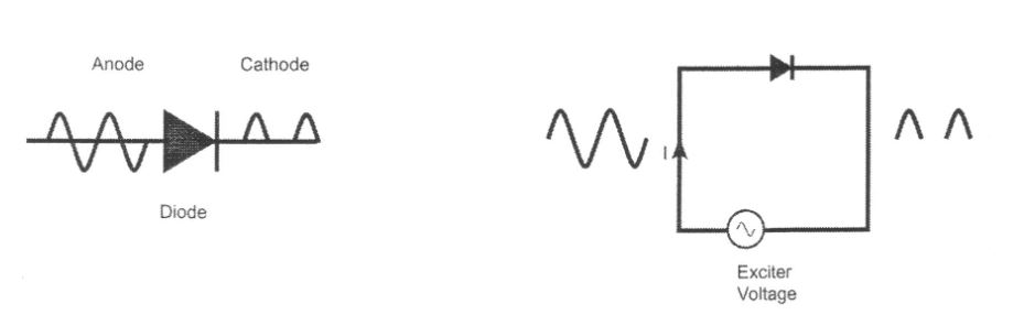
Diode
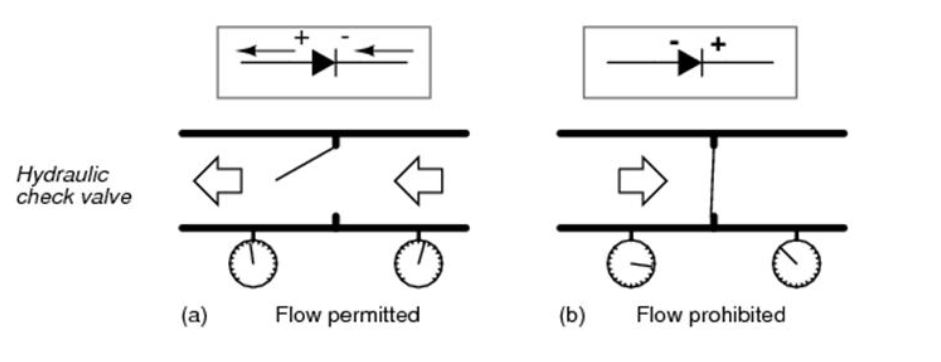
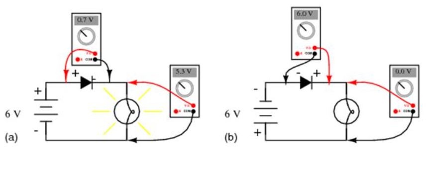
A diode functions by permitting electric current to flow in one direction while obstructing it in the opposite direction. It is commonly utilized to convert alternating current into direct current, a process known as rectification. Essentially, a diode can be likened to an electronic check valve.
Watch: The Diode
Watch “MAKE presents: The Diode” [7:25].
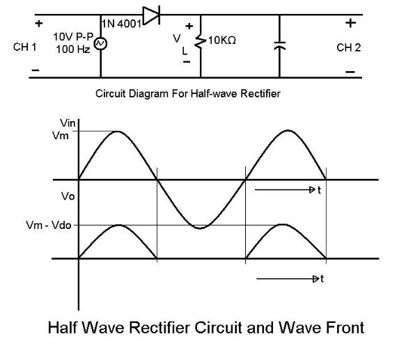
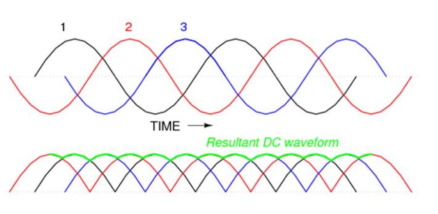
A diode comprises an anode and a cathode and, when subjected to AC voltage, conducts only one-half of the AC sinusoid. Consequently, a single diode yields DC voltage with notable ripples. In contrast, modern exciters are designed with 3-phase supply windings.
Three Phase Rectification
Activity: Brushless Exciter Start-Up Sequence
Click the tick marks on the slider to learn more about the start-up sequence of brushless exciters.