Part 2 – Constructional Details of DC Machines
Armature Reaction
Compensating Windings
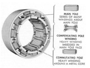
Compensating windings, also called pole-face windings, are used to reduce the effects of armature reaction. They have conductors embedded in the face of stator poles. The windings are arranged to be parallel to the armature windings.
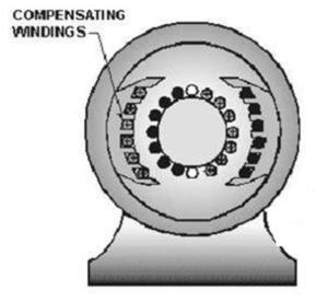
Compensating windings are wound to produce a field that opposes the magnetic field of the armature They cancel the effects of the armature’s magnetic field. The neutral plane will remain stationary and in its original position for all values of armature current. Once the brushes have been set correctly, they do not have to be moved again.
Interpoles
Interpoles, also called commutating poles, reduce armature reaction and improve commutation. An interpole has the same polarity as the following pole in the direction of rotation. They are wound in series with the armature so that the amount of field created is proportional to the armature current. Interpoles shift the neutral plane in the opposite direction of the armature reaction.
Activity: Interpoles
Click the arrows to view images of interpoles.
Activity: Windings
Click the tick marks to learn more about windings.
Armature Windings
Armature windings are wound into slots on a drum-type armature. Windings are then connected to the commutator.
Armature windings fall into the following categories:
- Lap
- Wave
Lap Windings
The ends of the coils are connected to commutator segments or bars.
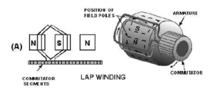
In lap windings, the number of parallel paths is always equal to the number of poles, and the number of brushes matches the number of poles. The armature coil ends are terminated on adjacent bars of the commutator, making lap windings well-suited for high-current DC generator applications.
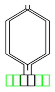
Wave Winding
In wave windings, the coil ends are connected to commutator bars spaced apart by the distance between poles. This winding configuration requires only two brushes (a single brush pair), although additional brush pairs can be employed if needed. The brushes are positioned at intervals corresponding to the distance between poles, resulting in a consistent two parallel paths. Wave windings are commonly utilized in high-voltage applications.