Part 1 – Magnetic Fields of AC Motors
AC Motors
Slide 3-4
AC motors can be broken into two broad classifications:
- Single-phase motors
- Single-phase power is available in residences, commercial and institutional buildings as well
Single-phase motors are the most common motors in use today.
Three-phase motors are known for their simple construction, ruggedness, and high efficiency. They are widely used in industry because three-phase power is readily available, making them the preferred choice in industrial applications.
AC motors consist of two basic parts:
- An outside stationary stator that has coils supplied with AC current to produce a rotating magnetic field.
- An inside rotor is attached to the output shaft that is given a torque by the rotating field.
With AC currents, we can reverse field directions without having to use brushes.
Disadvantages of brushes:
- Arcing
- Ozone production
- Ohmic loss of energy from brushes
- Brushes wearing out
There are two types of AC motors, depending on the type of rotor used.
Synchronous Motor:
- Rotates exactly at the supply frequency or a submultiple of the supply frequency.
- The magnetic field on the rotor is either generated by current delivered through slip rings or by a permanent magnet.
Activity: Synchronous Motors
Complete the activity below to learn more about synchronous motors.
Induction Motor:
- Turns slightly slower than the supply frequency.
- The magnetic field on the rotor of this motor is created by an induced current.
Video: Asynchronous Induction Motor
Watch “Asynchronous Induction Motor. How does it work.avi” [4:57].
Ordinary AC from a 2 or 3-pin socket is single-phase AC, characterized by a single sinusoidal potential difference generated between only two wires – the active and neutral.
Squirrel Cage Motor
Video: Squirrel Cage Motors
Watch “Squirrel Cage Motors.MGP” [2:10].
The rotor consists of a stack of steel laminations with evenly spaced conductor bars around the circumference.
Squirrel-Cage Rotor
Laminations are stacked together to form a rotor core. Aluminum is die-cast in the slots of the rotor core to form a series of conductors around the perimeter of the rotor. Current flow through the conductors forms the electromagnet. The conductor bars are mechanically and electrically connected with end rings. The rotor core mounts on a steel shaft to form a rotor assembly.
Slide 14 15 16 17
Rotor
A coil of wire on a rotor produces more torque than a permanent magnet rotor. As the applied single-phase AC voltage builds up, so does the strength of the stator field. The amount of current depends on the resistance of the coil of wire. The current flowing in the rotor sets up a magnetic field that opposes the stator field. Produces the torque that causes the rotor to turn.
Slide 20
Three-Phase Motor Rotating Stator Field
A three-phase motor’s stator features a rotating stator field, comprising three single-phase pole pairs positioned 120 degrees apart, with a 120-degree electrical separation between the voltages in each phase.
Slide 23 and 24
Three-Phase Rotating Stator Field
Three-phase AC induction motors are commonly employed, particularly for higher-powered applications. They do not require any special starting mechanisms.
Rotor and Stator Construction
The basic components of an A.C motor are the:
- Rotor
- Stator
Slide 27 and 28
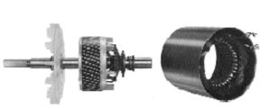
The complete rotor assembly consists of:
- Shaft
- Bearings
- Laminated iron core
- Rotor bars
Slide 30
Stator
Made from laminated sheets of steel. Slots are embedded in the inner surface. Stator windings are evenly wound around the slots. After the coils are set into the slots, the entire stator assembly is coated with varnish or epoxy resin.
The air gap between the rotor and stator is kept to a minimum Air is a poor conductor of magnetic flux. Air gaps range from 1.25 mm in small motors to 2.5 mm or more in large motors.
Motor Speed, Slip, And Torque
The speed of AC motors depends on the frequency of the applied voltage and the number of poles wound on the stator. Increase the frequency and the motor will turn faster. Increase the number of poles and the motor will turn slower. The difference in speed is called slip.
Slip
Slip is vital for generating torque and is load-dependent. Increased load leads to reduced rotor speed or higher slip, while decreased load results in increased rotor speed or reduced slip.
Activity: Motor Slip
Complete the activity below to learn more about motor slip.
The speed at which the stator field is rotating (or pulsating) must be greater than the speed of the rotor. Without induction, the motor will not work. If the rotor and the rotating magnetic field were turning at the same speed no relative motion would exist between the two, therefore no lines of flux would be cut, and no voltage would be induced in the rotor.