Part 1 – Alternator Rotors
AC Generators
AC generators are also called alternators. Both DC and AC generators produce alternating current. The main difference between the two types of generators is that the AC generator uses slip rings and the DC generator uses a commutator.
Activity: Generators
Click the arrows to see images of generators.
Voltage output for any generator depends on:
- Number of conductors
- Length of the conductor
- Generator speed
- Field strength
All electrical generators, regardless of their size or whether they are DC or AC, rely on the fundamental principle of magnetic induction. In this process, an electromotive force (emf) is generated when either a coil cuts through a magnetic field or a magnetic field cuts through a coil. As long as there is relative motion between a conductor and a magnetic field, a voltage is induced in the conductor.
AC generators are composed of:
- Field: which produces the magnetic field.
- Armature: is the part in which the voltage is induced.
All generators must have two mechanical parts:
- Rotor: the ROTor is the part that ROTates.
- Stator: the STATor is the part that remains STATionary.
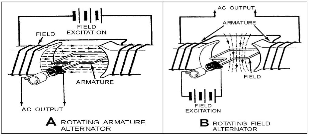
In a DC generator, the armature is always the rotor while in alternators, the armature may be either the rotor or stator.
Alternator Rotors
Alternator rotors serve the purpose of creating the essential magnetic field required to generate voltage in the stator windings, effectively transforming the rotor into a substantial rotating electromagnet.
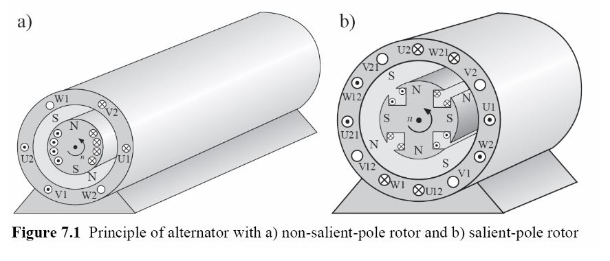
There are two distinct types of AC generator field rotors:
- Salient-pole rotor
- Cylindrical rotor
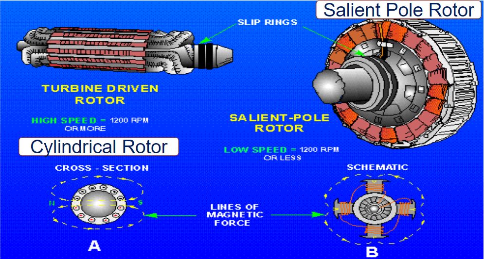
Salient-Pole Rotor
This rotor design features multiple individually wound pole pieces bolted to the frame, making it suitable primarily for low-speed applications, as it generates substantial centrifugal forces due to the protruding poles. Typically employed in applications with speeds less than 1200 revolutions per minute, with field conductors connected to slip rings.
Activity: Salient Pole Rotor
Click the arrows to learn more about salient pole rotors.
Salient Poles Designs
These designs are typically found in large applications like hydro generators, often with many megawatts of power output, as well as in smaller, higher-speed machines, usually with capacities up to 1-2 megawatts. These designs offer the advantage of being constructed in pieces and later assembled. In this configuration, each pole of the machine features its own field winding, which is securely bolted onto the rotor shaft.
Each pole consists of a winding, which can be constructed separately from the rotor. The winding is then placed around a pole body, and a “pole face” is bolted on top. Notably, the pole face may feature a different curvature than the stator surface, a design feature that contributes to a more sinusoidal flux density.
Activity: Salient Pole Rotor Parts
Click the image hotspots to learn more about salient pole rotor parts.
The torque and power characteristics are different than those of round rotor machines. Usually, salient-pole rotors have a large diameter (up to approx. 15 m) at a small axial overall length (up to approx. 3 m). The rotor poles are usually screwed to an iron rotor body.
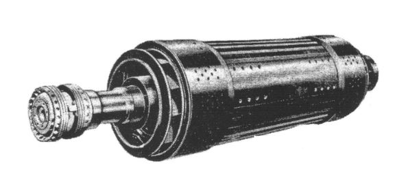
Cylindrical Rotors
Cylindrical Rotors: These rotor designs are primarily employed in high-speed applications, such as alternators driven by steam or gas turbines. The windings are securely embedded in slots to endure the considerable centrifugal forces experienced at high speeds. Windings are strategically arranged to create two or four distinct poles, with the field conductors connected to slip rings.
Video: 2 Pole Generator
Watch “2 pole generator” [0:51].
Activity: Cylindrical Rotor
Click the arrows to see images of cylindrical rotors.
Round-Rotor Machines
Round-rotor machines sound in higher speed higher power applications such as turbogenerators. They use 2 or 4 poles, these machines rotate at 3600 or 1800 rpm (with 60hz systems). Machine power is a function of the size of the machine.
Windage Loss
A force is created on an object by friction when there is relative movement between air and the object. Windage loss is the heat as a by-product of the friction.
Cylindrical Rotors
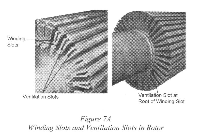
Cylindrical rotors are constructed from solid steel forgings, with dimensions that can reach significant sizes, including a 1-meter diameter, a 6-meter body length, shaft ends totaling 10.5 meters in length, and a mass ranging from 50 to 60 tonnes. The rotor’s body is slotted to accommodate windings, with each pole wound to create a concentric winding.
Activity: End Winding Before Fitting End Rings
Click the image hotspots to learn more about end windings.
Video: AC Machines
Watch “ge180part#1” [1:52].
Salient Pole disadvantages:
- Uneven air gap length could cause unacceptable turbulence in the air gap
- Centrifugal forces around the periphery of the machine make it difficult to maintain mechanical integrity.
The cylindrical design offers significantly greater strength and much lower windage losses compared to a salient pole machine.
Salient-Pole Rotors vs. Cylindrical Rotors
- Larger diameter than cylindrical rotors
- Shorter along the axial length than cylindrical rotors.
- Wound with many poles; cylindrical rotors – 2 or 4 poles
- Both types of generators are used to generate and supply 50 Hz or 60 Hz power.
The three main design constraints of alternator rotors are:
- Temperature
- Centrifugal forces
- Insulation of the rotor conductors
Stator
The stator, constructed of laminated high-quality magnetic silicon steel sheets, houses windings that supply power to electrical loads. To minimize magnetic and eddy current losses, both sides of each sheet are varnished.
Windings
The windings consist of copper bars insulated with mica on glass fiber tape. These bars are securely held in individual slots with wedges. The stator’s design includes slots that enable cooling air or hydrogen gas to flow freely, dissipating heat effectively.
Activity: Stator
Click the arrows to learn more about stators.
AC Generator
AC generators are often called synchronous generators. The main limitation to output is the amount of heat that can be dissipated from the machine.