Part 4 – Inductive Circuits
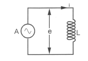
Inductors
Inductors differ from resistors in their behavior. Resistors resist electron flow by generating a voltage directly proportional to the current, while inductors resist changes in current by producing a voltage directly proportional to the rate of change of the current.
Video: The Inductor
Watch “MAKE presents: The Inductor” [10:45].
The induced voltage, often referred to as dropped voltage, consistently maintains a particular polarity in its attempt to uphold the current at its current level. When the current is in the process of increasing in magnitude, this induced voltage exerts a force that opposes the electron flow. Conversely, when the current is decreasing, the polarity of the induced voltage reverses, effectively pushing along with the electron flow to counteract the decrease. This resistance to changes in current is termed reactance, distinguishing it from the concept of resistance.
One way to visualize the action of an inductor is to imagine a narrow channel with water flowing through it and a heavy water wheel that has its paddles dipping into the channel. Imagine that the water in the channel is not flowing initially. Now you try to start the water flowing. The paddle wheel will tend to prevent the water from flowing until it has come up to speed with the water. If you then try to stop the flow of water in the channel, the spinning water wheel will try to keep the water moving until its speed of rotation slows back down to the speed of the water. An inductor is doing the same thing with the flow of electrons in a wire; an inductor resists a change in the flow of electrons.
Voltage/Current/Power In Purely Inductive Circuits
The curve of the applied voltage can be drawn exactly equal and opposite to that of the Induced E. Since the E is sinusoidal, the wave of applied voltage must also be a sine curve.
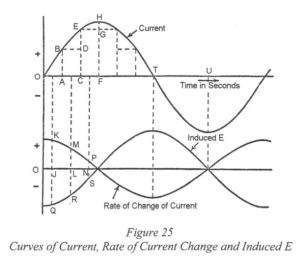
Activity: Curves of Current
Click the tick marks to learn about the rate of current change and induced E.
Second quarter-cycle
- Current decreases.
- The rate of increase of current is negative.
- Induced E becomes positive, tending to prevent the current decreasing.
- The value of the induced E increases from zero at F to a maximum at T and then decreases to zero at U.
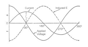
The voltage applied to a purely inductive circuit leads a quarter of a cycle or 90° in front of the current
The applied voltage is neutralized by the induced E. The current has to vary at such a rate that the E induced by the corresponding variation of flux is equal and opposite to the applied voltage.
Power in a Purely Inductive Circuit
Current increases from zero to its maximum value, Im, in a quarter of a cycle. If the frequency is f Hz, the duration of one cycle is 1/f second. The duration of a quarter of a cycle is 1/(4f) second.
Power in a Purely Inductive Circuit
The average rate of increase of current during the quarter of a cycle:
= Im ÷ 1/(4f)
sort = 4f Im amps/sec
Average E of Induced Voltage
= -L x 4f Im volts
Average E of Applied Voltage
Equal in magnitude to E Induced but in opposite direction.
= L x 4f Im volts
- f = frequency (Hz)
- L = inductance (Henrys)
For a sinusoidal wave:
The average value of voltage = 4f L Im
or Average value of voltage = (0.637) x max value of voltage (Em)
= (2/π) x Em
Therefore, 2/π x Em = 4f L Im
sort Em/ Im = 2 π f L
If E and I are the rms values of the applied voltage and current,
![\[ \huge \frac{E \text{ volts}}{I \text{ amperes}} = \frac{0.707 E_m}{0.707 I_m} \]](https://ecampusontario.pressbooks.pub/app/uploads/quicklatex/quicklatex.com-4eda2b5841555f014b9e151cc78ff2c4_l3.png "Rendered by QuickLaTeX.com")
= 2 π f L ohms
= inductive reactance (XL)
Inductive reactance
XL = 2 π f L ohms
Where:
- f = frequency (Hz)
- L = inductance (Henrys)
- π = 3.1416
Reactance is the ratio of the voltage to the current, it is expressed in ohms and represented by the symbol XL.
XL = 2 π f L ohms
This can also be expressed:
![\[ \large \text{Current } I \text{ amps} = \frac{E \text{ volts}}{2\pi fL \text{ ohms}} = \frac{E \text{ volts}}{X_L \text{ ohms}} \]](https://ecampusontario.pressbooks.pub/app/uploads/quicklatex/quicklatex.com-389ee54786c7a7efb8baee289f556a1d_l3.png "Rendered by QuickLaTeX.com")
or E = I x XL
or XL =E/I