Part 3 – Circuit Breaker Operation
Circuit Breakers
A circuit breaker is an automatically-operated electrical switch designed to protect an electrical circuit from damage caused by overload or short circuit. It’s basic function is to detect a fault condition and to immediately discontinue electrical flow by interrupting continuity.
Arc Control
Activity: Visit this YouTube Channel
![]()
Visit the GEArchFlashInnovation YouTube Channel to see videos on GE products that address the need to provide greater flash protection.
An arc is produced when a circuit is broken by the breaker. The arc is drawn across the current carrying contacts of the breaker as they are separated by the tripping mechanism. The rate of change in current that occurs when the circuit is broken can induce extremely high voltages that can ionize air and maintain the arc; this is known as restriking voltage.
An Arc Extinguisher is the component of the circuit breaker that extinguishes an arc when the contacts are opened. An arc is a discharge of electric current crossing a gap between two contacts.
Circuit breakers must be designed to control them because arcs cannot be prevented. There are four techniques to extinguish an arc:
- Stretching Arc
- Breaking Arc into Smaller Pieces
- Blowing Out Arc
- Enclosing Contacts
Arc Control Methods
There are six methods used for arc control. Two most commonly used methods are arc chute and vacuum interrupter. The other four methods are: SF6, Minimum oil, Magnetic coil, and Puffer.
Arc Chute
- Breaking Arc into Smaller Pieces technique
- Normally associated with low voltage circuit breakers due to efficiency and cost.
- There is one arc chute for each set of contacts.
AirBlast Circuit Breakers
AirBlast Circuit Breakers are used only on extra high voltage systems with standard ratings up to 765,000 V. They depend on a stream of compressed air that is directed toward the interrupting contacts to interrupt the arc formed. It removes all ionized matter from the gap between circuit-breaker contacts in a few microseconds. The gases removed are replaced by cooler air which also helps in cooling the arc.
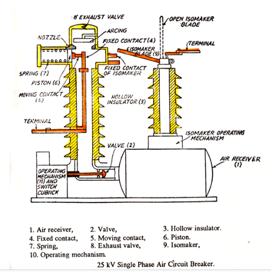
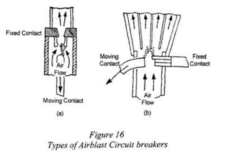
There are two main types of airblast breaker: Axial blast and Cross blast.
Axial blast
The arc is enclosed in the main air stream and subjected to severe constriction while the high velocity of the air over the electrode surfaces subjects the arc roots to the maximum possible scavenging action. Only necessary to draw the contacts apart a distance sufficient to withstand the maximum value of the restriking voltage transient with the air pressure on.
Activity: Click through the images to see the types of arcs.
Arc Chute Method
Activity: Click through the images.
Vacuum Interrupter
Uses the Enclosing Contacts technique to extinguish arcs. Vacuum enables the contacts to be smaller and eliminates the divider, making this method the most cost effective and efficient above 1000V. Arcing takes place within a sealed evacuated enclosure. One vacuum interrupter is provided for each set of contacts.
Vacuum Interrupter Examples
SF6 Method
The SF6 Method uses the Enclosing Contacts technique. Precursor to the vacuum interrupter and used SF6 gas as the dielectric. Heat energy created by the arc works to break apart the SF 6 molecules. The larger the arc, the greater the breakdown of the gas which aids in extinguishing the arc.
SF6 Method Examples
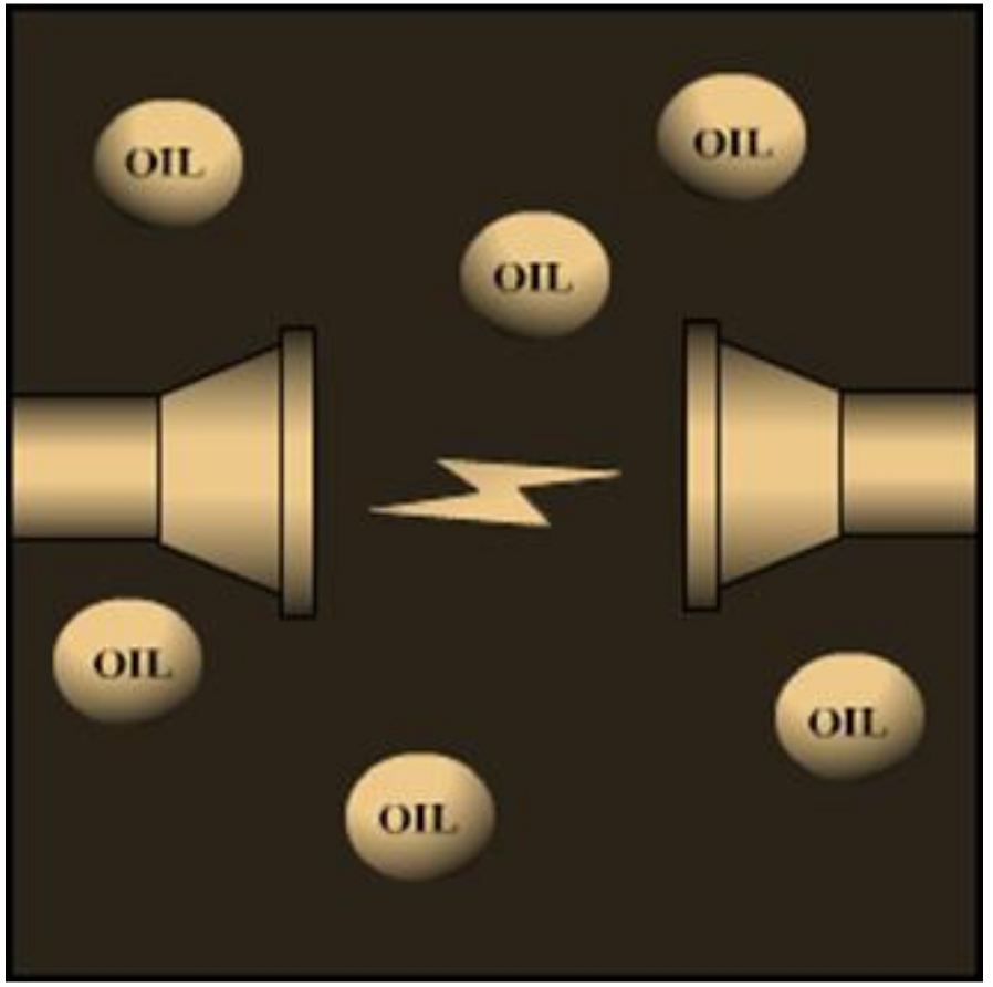
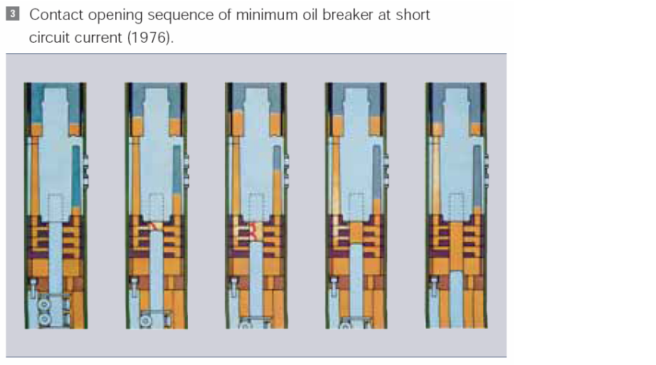
Minimum Oil method
The Minimum Oil Method uses Enclosing Contacts with oil as the dielectric. Arc energy is absorbed as it rips hydrogen away from the oil molecule. Oil itself also helps to cool the arc. Used today in low voltage situations and potentially explosive environments where an arc chute is not desirable.
Activity: Click on the image to browse components of a minimum oil breaker, three phase circuit breaker, cross section through a single phase.
Oil-Immersed Circuit Breakers
The oil serves three purposes:
- To insulate the arc from grounded (earthed) metal and to confine it.
- To provide adequate cooling to the breaker contacts.
- To provide some arc control by the natural pressure of a head of oil.
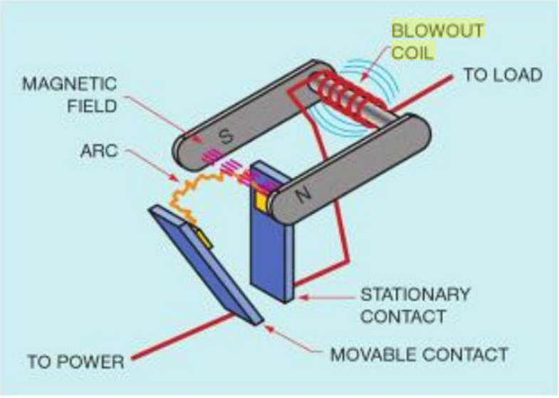
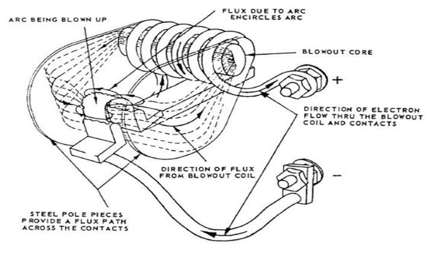
Magnetic Coil method
The magnetic coil method uses the Breaking Arc into Smaller Pieces technique, similar to the arc chute method. A coil, called a blowout coil, is located in the center of the arc chute. The arc is broken into two. The arcs are lengthened and cooled as they rise higher.
Puffer Method
Pair of separable contacts, a piston and a cylinder, mounted in a reservoir of gas. As the contacts part, the piston moves up to drive the gas through the arc to interrupt it. Also uses coils and takes advantage of natural magnetic affects to create a force sufficient to extinguish the arc.
Activity: Click through the images.
Air-Break Circuit Breaker
Large air circuit breakers use springs as a fast, positive closing action. Energy is stored by compressing powerful springs which are linked through a latching mechanism to the breaker’s contact assembly. Once the springs are compressed, the breaker contacts close quickly. A manually operated hand crank or a small electric motor is used to compress the breaker-closing springs.
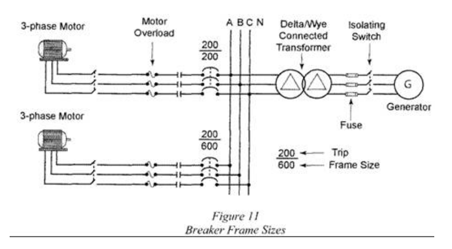
Frame Size
Breakers are manufactured in frame sizes. The National Electrical Manufacturers Association (NEMA) defines a frame as group of common parts which can include an interchangeable trip unit. Refers to the maximum size of the trip unit that may be installed in the unit.
Functions
These breakers perform the following functions:
- Sense when an overcurrent occurs.
- Measure the amount of overcurrent.
- Act by tripping the circuit breaker in a time frame necessary to prevent damage to itself and the associated load cables.
The breakers use the following mechanisms to automatically open the circuit:
- Thermal
- Magnetic
- Electronic
- Instantaneous
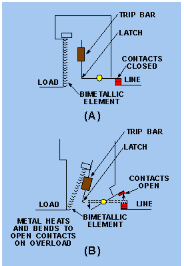
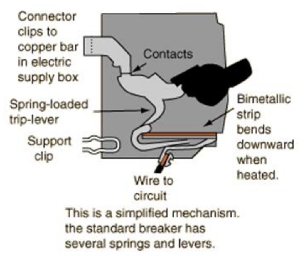
Thermal Mechanism
Bimetal strip that heats during an overload condition. Breaker can be reset after the source of the fault is removed from the circuit and after sufficient time has passed for cooling.
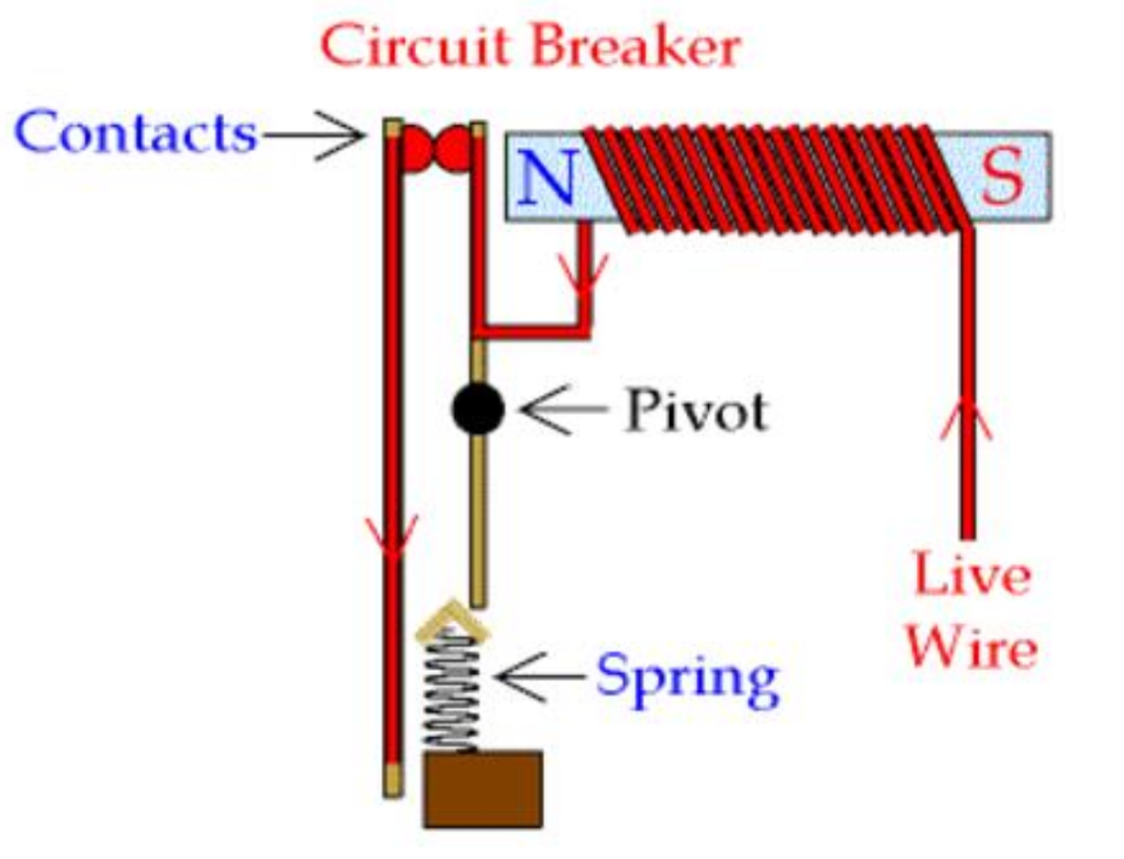
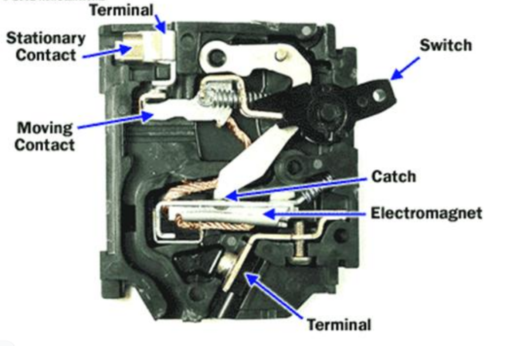
Magnetic Mechanism
Solenoid or electromagnet. Large overload current or short-circuit current will generate enough flux to operate the solenoid and trip the breaker. Moulded-case breakers often employ a combination of thermal and magnetic trips to provide overload and short-circuit protection. Commonly called thermal-magnetic breakers.
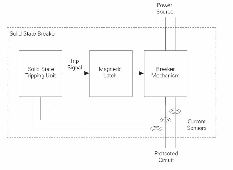
Electronic Trip
Solid state circuit breakers function similarly to thermal-magnetic breakers. Basic breaker mechanism is mechanical. The tripping unit is solid state. Electronic trip mechanism is adjustable, usually through a dial setting found on the front of the breaker.
Instantaneous Trip
Designed only for short-circuit protection. Trips instantaneously under short-circuit conditions. Commonly used in motor circuits, but it must be used in combination with a motor overload device.
Maintenance of High-Voltage Breakers
Need to be inspected regularly and whenever the unit has operated due to overcurrent. Manufacturers recommend complete inspections, including oil testing where applicable, every 6 to 12 months for circuit breakers above 15 kV.