Part 8 – Instrument Transformers
Instrument transformers fall into two categories: current transformers and potential transformers. They are used to transform either the current or the voltage to a safe level so that it can be easily used in the above systems. Instrument transformers are used in conjunction with metering systems, measuring systems, and protective relaying systems.
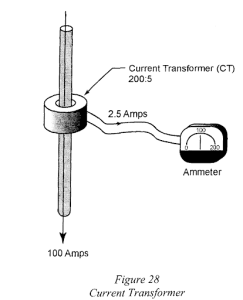
Current Transformers (CT)
Current Transformers (CT) provide a signal that is proportional to the amount of current flowing in a conductor. They are one-winding transformers and are always stamped with a ratio, for example, 200:5.
If there is current flowing in the main, the current transformer coil will step down the voltage to be read on an ammeter. (i.e., If 100 A is flowing in the main conductor, then 2.5 A will flow in the circuit to the ammeter.)
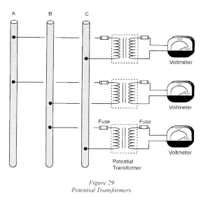
Potential Transformers (PT)
Potential Transformers (PT) provide a voltage signal that is proportional to a larger voltage. The secondary voltage of potential transformers used for metering purposes is 120 V.
In the diagram below, three potential transformers are connected to a three-phase 600 V system. Potential transformers step the voltage down to a safe level of 120 V and the electrical codes require that the transformers be protected with fuses.