Part 1 – Shell and Core Transformers
A transformer is a device that transfers electrical energy from one circuit to another by electromagnetic induction (transformer action). Electrical energy is always transferred without a change in frequency, but may involve changes in magnitudes of voltage and current. Transformers works on the principle of electromagnetic induction and must be used with an input source voltage that varies in amplitude (AC). A transformer is a device that transfers electrical energy from one circuit to another through inductively coupled electrical conductors.
Operation
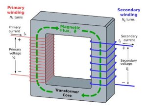
The operation of a transformer consists of two windings or circuits. Changing the current in the first circuit (the primary) creates a changing magnetic field and induces a changing voltage in the second circuit (the secondary).
Activity: Transformer Voltage and Windings
Click on the link to go on Molecular Expressions website to play around and adjust a transformer input voltage, and primary and secondary windings.
Small Transformers
Small transformers are used for low-voltage power supplies found in computers, consumer electronics, and small appliances.
Transformers are also used to step down the voltage to safe levels for use in industry and households.
Large Transformers
Large transformers are used to step up the voltage from generators at power generating stations to voltage levels used to transmit power to substations located near cities and towns.
Power transformers are large-capacity transformers used in generating stations and substations that are custom-built for the power requirements of the application and are rated above 500kVA.
Distribution transformers are another large transformer that are generally smaller in capacity than power transformers and are mass-produced in common sizes and are rated between 3kVA and 500 kVA.
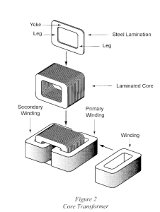
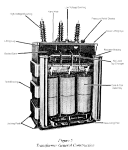
Transformer Construction
The construction of a transformer consists of a primary coil or winding, a secondary coil or winding, and a core that supports the coils or windings. Windings are electrically isolated from each other but are magnetically connected.
The iron or steel laminated core provides a path for the magnetic flux generated by the current flowing through the windings and transformers often have an efficiency of more than 95% but a working transformer is usually warm or even hot. The heat generated is due to the losses of the transformer.
By varnishing each lamination, improves the efficiency by reducing eddy currents. Some magnetically soft metal is used for the laminations are low-carbon steel, silicon steel, nickel-iron, cobalt-iron-nickel, and cobalt-iron. Transformer construction falls into two general classifications which are core and shell.
Transformer Core |
Transformer Shell |
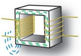
Transformer Core
The core design is used for high-voltage transformers which this configuration is easier to insulate and to cool.
 |
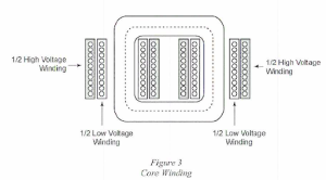
Half the high voltage winding and half the low voltage winding are wrapped around each leg. |
A single-phase transformer consists of a core (usually laminated steel), a primary winding, and a secondary winding. A time-varying current in the primary coil produces a time-varying magnetic field. This time-varying magnetic field induces a voltage in the secondary coil. This is due to the principle of Faraday’s law of induction.
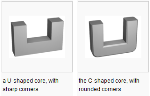
U and C Shaped Cores
U and C-shaped cores are used with I or another C or U core to make a square closed core, the simplest closed core shape. Windings may be put on one or both legs of the core.
E Shaped Cores
E-shaped core are more symmetric solutions to form a closed magnetic system. Most of the time, the electric circuit is wound around the center leg, whose section area is twice that of each individual outer leg.

Core Construction Uses Two ‘E’ Cores
 |
 |
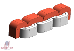
Three-Phase Core-Type Transformer
A three-phase core-type transformer is widely used in power transmission. The core-type has more room for insulation and therefore can handle higher voltages.
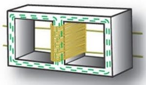
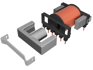
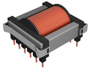
Transformer Shell
Both windings are wound around one central leg and the coil assembly is made first. A steel-laminated core is assembled around the coil. More efficient in channeling core flux, so fewer turns are required.

Construction costs for transformer shell types are cheaper, but ventilation of the shell-type design is often more difficult. Most small power transformers are shell-type.
Windings
Windings are made of copper for its electrical conductivity, corrosion, and thermal conductivity properties. Each conductor is individually insulated and the amount of insulation depends on the voltage level of the transformer and whether the construction is shell-type or core-type. Insulation may consist of a varnish coating or a cellulose layer between the windings. All primary and secondary coils are assembled and insulated from each other.
Transformer Output
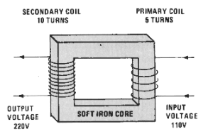
Proportional to turns for primary coils, the strength of the magnetic field is in proportion to the input voltage and the number of turns around the core, and for secondary coils, the output voltage is proportional to the strength of the changing magnetic field and the number of turns.
Output is proportional to turns: input volts/input turns = output volts/output turns.