Part 7 – Parallel Operation of Generators
Power Factor
The power factor (pf) is determined by the characteristics of the load connected. When one alternator supplies the load, the power factor is also that of the load. However, when two or more alternators are used, the power factor of each can be controlled individually by adjusting the exciter.
If the generator is under-excited, the power factor becomes leading. The current output increases without any change in the kW output. Control of the alternator power factor is typically done by manually adjusting a trimming resistance in the voltage regulator circuit.
Parallel Operation
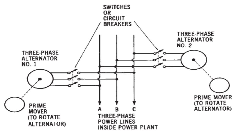
Generators must be synchronized as closely as possible before connecting them together, which is accomplished by connecting one generator to the bus (referred to as the bus generator) and synchronizing the incoming generator to the bus generator before closing the incoming generator’s main power contactor.
If a generator operating in parallel is overexcited:
- The power factor will change in the lagging direction.
- Current output increases without appreciable change in kW load output.
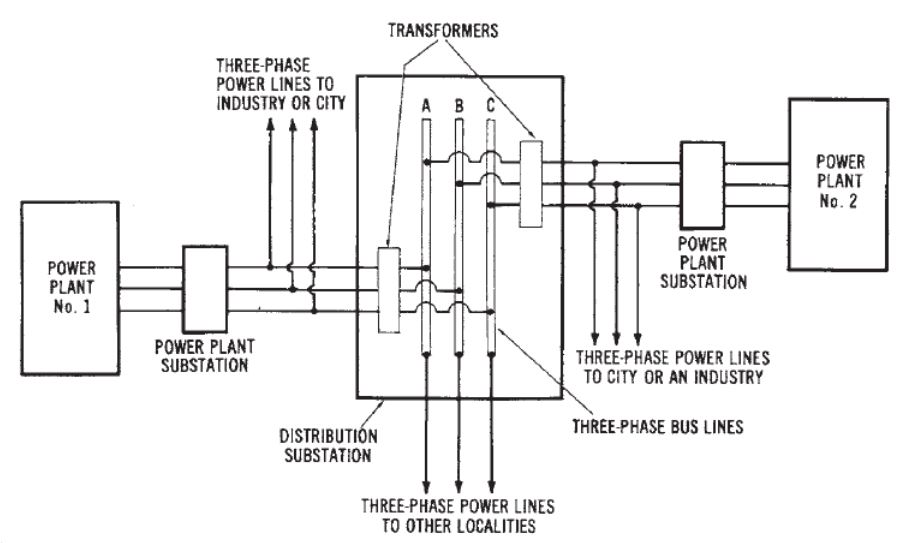
The major problem of parallel-connected distribution systems:
- Occurs when excessive load demands are encountered by several power systems in a single region.
- If all of the power plants in one area are operating near their peak power-output capacity, there is no backup capability.
- The equipment protection system for each power plant, and also for each alternator in the power plant, is designed to disconnect it from the system when its maximum power limits are reached.
- When the power demand on one part of the distribution system becomes excessive, the protective equipment will disconnect that part of the system. Places an even greater load on the rest of the system.
- The excessive load now could cause other parts of the system to disconnect.
- The cycle could continue until the entire system is inoperative. This is what occurs when blackouts of power systems take place.
Synchronism
Two generators or a generator and a system are synchronized when the following conditions are set:
- Equal terminal voltages
- Equal frequency
- Phase voltages in proper phase relation
- Phase sequence must be the same
Synchronizing Conditions
Condition 1
- Ensure that terminal voltages are equal.
- Adjust terminal voltage using a voltage regulator or rheostat to match the system voltage.
- Confirm that the machine is operating at the required speed.
Condition 2
- Confirm that frequencies are equal.
- Adjust the frequency of the alternator by controlling the speed of the prime mover.
Condition 3
- Ensure that the phase sequence (rotation) is consistent.
- This can be verified using either lamps or a phase rotation meter, or by connecting a polyphase induction motor alternately to the system and the incoming machine.
Activity: Phasing Out Polyphase Alternators
Click the ticks on the slider to learn more about phasing out polyphase alternators.
Activity: Phase Rotation
Click the tick marks to learn more about phase rotation.
If the direction of rotation of the motor is the same when connected to the incoming alternator and then when connected to the system, then the phase rotation is the same.
Condition 4
Voltage must be in phase, and synchroscopes are the most common method.
Activity: Steps Taken to Synchronize an Incoming AC Generator to the Supply System
Click the accordion to learn the steps to synchronize an incoming AC generator to the supply system.
Synchronizing Generator
The incoming generator is running at its rated speed, with its circuit breaker open. The synchronizing switch is closed to facilitate the adjustment of the incoming generator’s voltage, which is done by regulating the generator field excitation to match the bus voltage. A synchroscope is used to ensure that the generator voltage is in phase with the bus voltage and that the frequencies of the generator and the bus are synchronized.
To fine-tune the generator frequency, the speed of the prime mover can be increased or decreased. When the synchroscope pointer comes to a stop in a vertical position, it indicates that the generator and the system voltage are identical. At this point, the circuit breaker can be closed.
Adjust the frequency to closely match the desired level, then close the breaker just before the synchroscope pointer approaches the vertical position and begins to move slowly in the “fast” direction. This action ensures that the incoming generator gradually takes on a small load, allowing the parallel generators to remain stable.
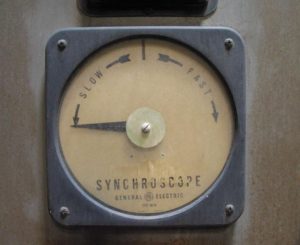
Synchroscope
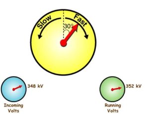
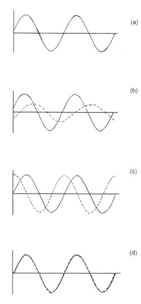
The synchroscope provides a clear understanding of the phase relationship between the incoming machine’s voltage and the system’s voltage. It indicates this by the rotation of the pointer in the “fast” direction when the incoming machine’s frequency is greater than the system’s, and in the opposite direction when the incoming machine’s frequency is slower. When the frequencies match, the pointer remains stationary. This operation is achieved through the interaction of magnetic fields from two circuits: one connected to the alternator and the other to the system, acting upon a soft iron vane or disc with the attached pointer.
Automatic Synchronizing Equipment
Automatic synchronizing equipment ensures the automatic synchronization of the incoming generator with the main bus. It comprises several key components, including:
- Speed matching relay
- Voltage matching relay
- Synchronizing relay
- Auxiliary relays
- Transfer relays or switches
Power Factor Control
When two alternators are running in parallel, a transfer of load between them results in a voltage differential.
Effects of Reactive Power on Apparent Power
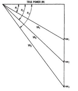
A low power factor (increase in vars) causes more power to be generated than used. Significant cost to businesses using a lot of electric motors.
Alternator with reduced kilowatt loading:
- Internal voltage increased because fewer voltage drops within its stator windings
- The machine is said to be over-excited for the new value of load.
Alternator with the increased kilowatt loading:
- Internal voltage decreased because of the increased voltage drops in the stator.
- The machine is said to be under-excited for the new value of load.
In a system where the power factor is unity, the maximum power factor value is 1.0, or 100%, and it is achieved in a purely resistive circuit.
In a system with a lagging power factor, there is a disproportionate division of reactive power among the alternators. An over-excited machine will supply more Vars, resulting in a lagging power factor, while an under-excited machine will exhibit a leading power factor.
The balancing of Vars between the machines is achieved by adjusting the field excitation of each machine. To do this, the field rheostat of the under-excited machine is turned in the raise voltage direction, while the field rheostat of the over-excited machine is turned in the lower voltage direction. These adjustments are made until the power factor meter readings are identical on both machines.
Activity: Power Factor
Click the tick marks to learn more about the power factor.
The average system load:
- Induction
- Resistance
- Some capacitance
The system is usually between unity and 0.8 lagging.