Part 5 – Alternator Cooling Systems
Alternator Cooling Systems
In larger alternators, the increased power and magnetic losses result in higher heat production that must be efficiently managed compared to smaller alternators. The cooling method used directly influences the physical size and structure of these alternators.
Fours types depending on the volt-amp output of the unit:
- Direct Air
- Enclosed Air
- Hydrogen
- Water
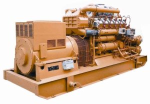
Direct Air Cooling
Small alternators employ rotor shaft-mounted fans for direct air cooling.
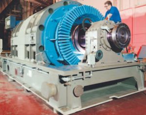
Enclosed Air Cooling
In larger generators, typically ranging from 25 to 325 MVA, enclosed air cooling is the method of choice. This approach involves separate fans to supply cooling air, with air filtration and return ducts designed to direct exhaust air back to the fans’ inlets. Additionally, air coolers with finned tubes circulate cooling water to dissipate heat effectively.
Water Cooling
Certain alternator designs employ water for cooling the stator windings. Cool, deionized water is supplied by a closed-loop auxiliary system and flows through copper strands in the stator winding. This cooling process begins as cool water enters the winding through a distribution header at one end of the generator, and warm water is discharged at the opposite end. Cool, deionized water, provided by a closed-loop auxiliary system, circulates through both the copper strands within the stator winding and the hollow, non-magnetic stainless steel conductors that carry the cooling water.
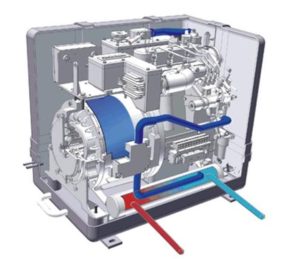
Water cooling systems are more complex and more costly than conventional systems, the cost is offset by a significantly smaller physical size.
Activity: Water Cooling
Click the arrows to see images of water cooling systems.
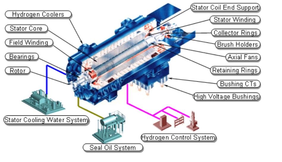
Hydrogen Cooling
Hydrogen cooling is applied in larger alternators, typically those with a capacity ranging from 200 to 1000 MVA. Comparatively, the operation, installation, and maintenance of air-cooled generators are generally more straightforward than those of hydrogen-cooled generators. However, due to the reduced cooling efficiency of air, air-cooled machines of similar ratings require a 20% to 30% increase in size when compared to their hydrogen-cooled counterparts.
Advantages of hydrogen gas:
- High heat transfer coefficient, ensuring efficient cooling.
- Rapid absorption and rejection of heat as it flows through the generator windings.
- Lower density than air, requiring less energy for circulation through generator components.
- Minimizes windage, reducing braking effects on the alternator’s rotating parts.
In hydrogen cooling, the ventilation pattern for a specific design is contingent upon several factors, including the machine’s length and the temperature distribution within its various components, with special attention to the stator and field windings.
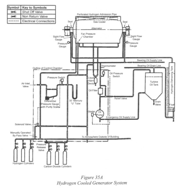
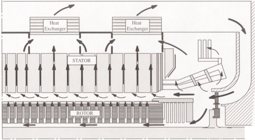
In hydrogen cooling systems, there are various designs for gas flow. Some configurations involve gas entry at both ends of the rotor with an exit at the center, while others have entry and exit points at opposite ends. Certain manufacturers employ rotor ventilation slots for gas entry, which then escapes radially through slotted conductors. To mitigate the risk of explosion resulting from hydrogen-air mixing, airtight casings and proper seals around the rotor shaft are employed. Additionally, a CO2 purge system is used.
The importance of keeping hydrogen free from moisture is multifaceted. Moisture can increase the viscosity of hydrogen, reducing its heat-carrying capacity and leading to seal deterioration on the rotating shaft. Thus, hydrogen-cooled machines require effective shaft sealing arrangements to prevent gas leakage.