Part 5 – DC Motor Operation
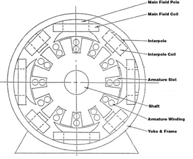
Armature
A torque (Newton-metres) is a force acting upon a radius. Force is developed on all the active armature conductors tending to turn the armature in a clockwise direction.
Total Torque developed by the motor in newton metres (Nm)
= (sum of the forces, N) x radius of the armature, m
T = F x r
- T – Torque N-m (Newton-metres)
- F – Force N (Newtons)
- r – radius m. (meters)
Rotation
The direction of rotation of a DC motor may be reversed by reversing either the field or the armature connections. If both are reversed, the direction of rotation remains unchanged.
The force developed is directly proportional to:
- Strength of the main field flux
- Strength of the field around each conductor. The field around each armature conductor depends on the amount of armature current flowing in that conductor.
Torque Developed
The torque developed by a motor:
T = KΦ Ia
Where,
- T = torque, newton metres
- K = a constant depending on the physical dimensions of the motor
- Φ = total number of lines of force per pole
- Ia = armature current, amperes
Back Electromotive Force
When the armature of a DC motor rotates under the influence of the driving torque:
- The armature conductors move through the magnetic field and an e.m.f. is induced in them as in a generator.
- The induced e.m.f. (voltage) acts in the opposite direction to the applied voltage V (Lenz’s law) and is known as back or counter e.m.f.
- The back e.m.f. is always less than the applied voltage V, although this difference is small when the motor is running under normal conditions.
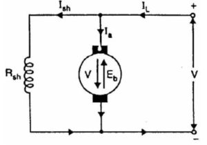
When DC voltage V is applied across the motor terminals:
- Field magnets are excited.
- Armature conductors are supplied with current.
- Driving torque acts on the armature which begins to rotate.
As the armature rotates, back e.m.f. Eb is induced which opposes the applied voltage V. The applied voltage V has to force current through the armature against the back e.m.f., Eb
The electric work done in overcoming and causing the current to flow against Eb is converted into mechanical energy developed in the armature. The energy conversion in a DC motor is only possible due to the production of back EMF.
The net voltage across the armature circuit = VT – Eb
Ia = (VT – Eb)/ Ra
Net voltage across armature circuit (Va)
Va = V – Eb
If Ra is the armature circuit resistance,
Ia = (V – Eb)/ Ra
Since V and Ra are usually fixed, the value of Eb will determine the current drawn by the motor.
Eb determines the current drawn by the motor, so:
- If the speed of the motor is high the back e.m.f. is large and the motor will draw less armature current.
- If the speed of the motor is low the back e.m.f. is small and the motor will draw more armature current.
When the motor is running on no load, a small torque is required to overcome the friction and windage losses. The armature current Ia is small while the back e.m.f. is nearly equal to the applied voltage.
If the motor is suddenly loaded the armature slows down while the back e.m.f., Eb, falls. The decreased back e.m.f. allows a larger current to flow through the armature and a larger current means increased driving torque while the driving torque increases as the motor slows down. The motor will stop slowing down when the armature current is sufficient to produce the increased torque required by the load.
The back e.m.f. in a DC motor regulates the flow of armature current. It automatically changes the armature current to meet the load requirement
The value of emf will depend on:
- Field strength
- Armature speed
The value of the back emf E that is generated in a motor is given as:
E = KΦn
Where,
- E – counter emf, volts
- n – speed of armature, rpm
- Φ – flux per pole, webers
- K – constant based on physical properties of motor
Note: The symbol used for magnetic flux is Φ (phi) and the unit is the Weber, Wb.
Effective armature voltage is the applied or terminal voltage minus the counter emf.
Armature current = applied voltage – counter emf/armature resistance
The armature current is:

Then,
Vt = Eb + IaRa
Where,
- Ia – armature current
- Vt – motor terminal voltage
- Eb– counter emf
- Ra – armature-circuit resistance
Example 1:
Find the counter emf of a motor when the terminal voltage is 600 V, and the armature current is 120 A. The armature resistance is 0. 99 Ω.
- Ia – armature current = 120 amps
- Vt – motor terminal voltage = 600 volts
- Eb – counter emf = ? volts
- Ra – armature-circuit resistance = 0. 99 ohms
Solution 1:
Vt = Eb + IaRa
Eb = Vt – IaRa
= 600 – (120 x 0.99)
= 600 – 118.8
= 481.2 V
Example 2:
Find the armature current of a shunt motor when the terminal voltage is 110 V, the counter emf is 108 V and the armature-circuit resistance is 0.03 Ω.
- Ia – armature current = ? amps
- Vt – motor terminal voltage = 110 volts
- Eb – counter emf = 108 volts
- Ra – armature-circuit resistance = 0.03 ohms
Solution 2:
Vt = Eb + IaRa


Ia=110 – 108/0.03
=2/0.03
= 66.7 A
Example 3:
The armature current of a shunt motor is 53.8 A when the terminal voltage is 40 V, and the armature-circuit resistance is 0.13 Ω. What is the counter e.m.f?
- Ia – armature current = 53.8 amps
- Vt – motor terminal voltage = 40 volts
- Eb – counter emf = ? volts
- Ra – armature-circuit resistance = 0.13 ohms
Solution3:
Vt = Eb + IaRa
Eb = Vt – IaRa
= 40 – (53.8 x 0.13)
= 33 V
Torque
The vector sum of the resultant magnetic forces multiplied by the radius of the armature measured in meters. Torque is measured in newton-metres (Nm).
The force exerted on a current-carrying conductor when in a magnetic field depends upon:
- Strength of the field
- Amount of current flowing
- Length of the conductor
The torque will be the sum of all these forces exerted on the individual conductors and can be expressed by the equation:
F = β x I x L
Where
- F = Turning force newtons
- β = Flux density, teslas
- L = Total length of conductors, meters
- I = Current in conductor, amperes
The Weber is the flux which when reduced to zero in one second produces one volt in a coil of one line lying in this flux.
β = magnetic flux density
β = the number of lines of flux (Φ) passing through a unit area A set at right angles to the flux
β = Φ/A
1 T (Teslas) = 1 Wb/m2 (Weber per square meter)
The length of the conductor is determined by
L = total length of conductor
= the number of conductors x % under pole face x length of armature (meters)
Example
The armature of a DC motor has 50 conductors of which 85% lie under the pole faces at any given instant. If the armature length is 66 mm, determine the total length of the conductor.
L = 50 x 0.85 x 66mm/(1000mm/m)
= 2.805 m
The armature of a DC motor has 900 conductors of which 83% lie under the pole faces at any given instant. The flux density under the poles is 0.5 T. If the armature diameter is 444 mm, its length is 222 mm and the current in each conductor is 66 amperes.
Find:
- The total force tends to rotate the armature
- The torque exerted by the armature
Solution:
β = 0.5 T
I = 66 A
L = 900 x 0.83 (83%) x 222/1000 (222 mm in m.) = 166 m.
r = armature diameter/2 = 444 mm/2 = 222 mm = 222/1000 m. = 0.222m
F = β x I x L
F = 0.5 x 66 x 166
= 5,478 N
Torque = Force x Radius = Fr
= 5,478 x 222/1000
= 1,216 Nm
Activity: Generators
Click the arrows to see images of generators.