Part 1 – DC Machine Construction and Operating Principles
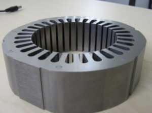
Stator
A stator is a mechanical device consisting of the stationary part of a motor or generator in or around which the rotor revolves.
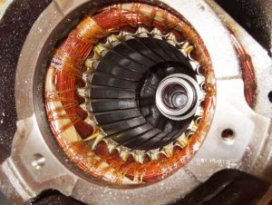
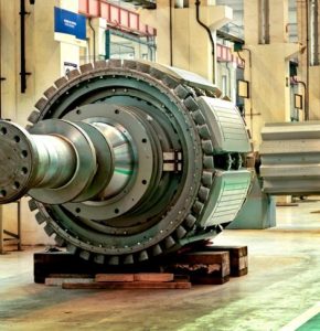
Rotor
A rotor is a rotating armature of a motor or generator.
Field
Fields are the stationary part of a dynamo.
DC Generators
The operation of a DC Generator is the same as an AC generator. An AC generator is called an alternator while a DC generator is called a dynamo.
Commutator
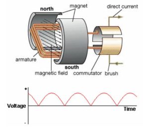
A commutator is a cylindrical arrangement of insulated metal bars connected to the coils of a direct-current electric motor or generator, providing a unidirectional current from the generator or a reversal of current into the coils of the motor.
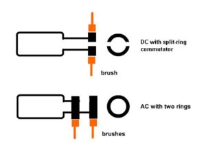
DC generators differ primarily in their commutator design. Commutation involves positioning the DC generator brushes to synchronize with the change in armature current direction.
Activity: Commutators
Click the arrows to view images of commutators.
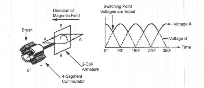
The commutator consists of a single slip ring split in half, with each half insulated and linked to opposite ends of the rotating coil. Brushes facilitate the flow of current to the connected load, ensuring that the coil permits current to exit in just one direction, following the right-hand rule for generators.
The commutator is responsible for producing pulsating DC voltage and current. To minimize this pulsating effect, additional poles, armature coils, and commutator segments are added.
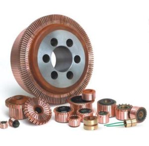
The commutator typically features twice as many segments as there are coils. For instance, if there are two coils, the commutator will have four segments.
The effective, or RMS, value of the voltage is higher when more coils are added to the armature.
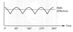
The ripple in the DC waveform can also be improved by adding more poles. More poles also provide a stronger field, and therefore a higher induced voltage.
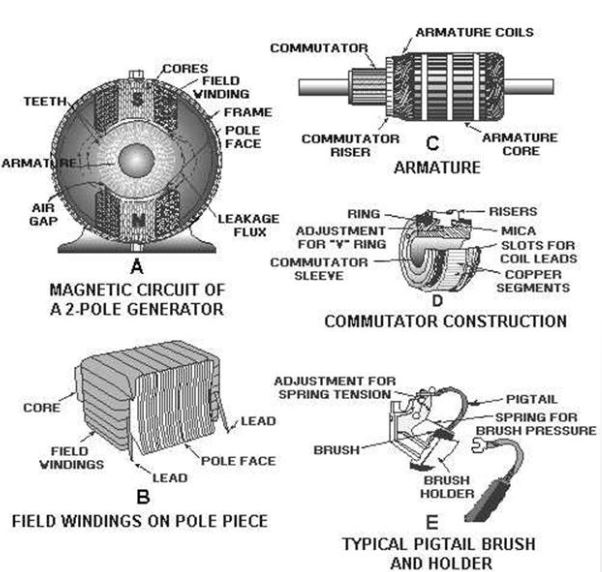
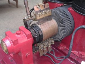
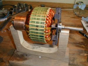
Armature
The armature is a rotating part of a dynamo, consisting essentially of copper wire wound around an iron core.
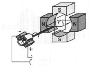
Armature reaction happens when the magnetic field produced by the current that flows in the armature coils of a DC generator affects the magnetic field of the poles mounted on the stator.
Activity: Armature Reaction
Click the arrows to learn more about armature reaction.
Commutation takes place at the point where the armature coil is moving parallel to the stator field. Improper placement of the commutator results in sparking when the coil segments transfer from one brush to the other. Good commutation occurs when the brushes of a generator are adjusted to compensate for the shift in the neutral plane.
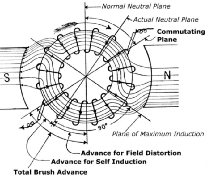
The effect of the armature reaction varies with the load current. Every time the load current varies, the neutral plane shifts this means the brush position must be changed each time the load current varies.
Two methods of neutralizing the cross-magnetizing effect of armature reaction:
- Compensating windings
- Interpoles