Part 1.2 – AC Voltage and Current
The Sine Function
Alternating Current
Alternating Current (AC) is the foundation of power systems where voltage and current continually fluctuate between positive and negative maximum values, with the sine wave function serving as a representation for these variations.
Activity: Sine Wave Function
Click the ticks on the slider to learn more about the sine function.
Vector Components
Vector components can be represented as the real and imaginary parts of complex numbers, where the real part corresponds to the cosine function and the imaginary part corresponds to the sine function. In alternating current analysis, these components are used to represent the amplitude and phase of the AC signal, with the sine component determining its oscillatory behavior over time. To calculate the vertical component of vector A, which has a length of 1.0 and is rotated 30°, trigonometry can be applied to determine the value within a right-angle triangle.
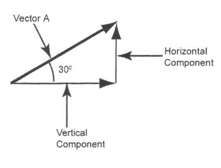
sin θ =  =
= 
Vertical component = sine 30° x Vector A = 0.5 x 1.0 = 0.5
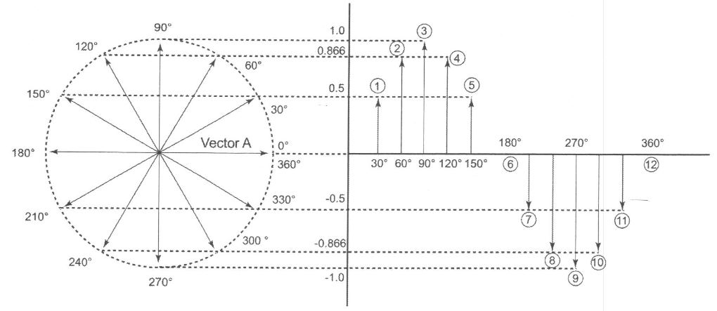
Rotating Vector
The sine wave is generated by rotating a vector and by considering the angle it makes with a reference axis.
Activity: Sine Wave
Click the arrows to see images of sine waves.
Electromotive Force
Electromotive Force (EMF), denoted by ℰ (epsilon), is a force that facilitates the movement of electricity from one point to another. This electrical potential is measured in volts (joules per coulomb in SI units) and can originate from various sources, including generators (both AC and DC types), batteries, and thermocouples.
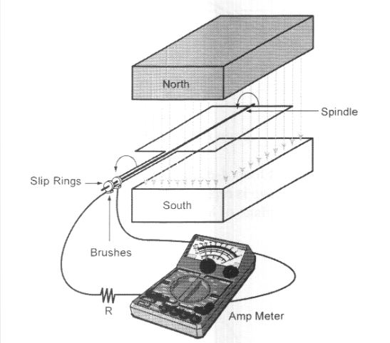
Generation of an Alternating EMF
Voltage is generated when a conductor intersects magnetic field lines, inducing a current flow through an external resistance R according to Ohm’s law (I = E/R). The rate of induction increases with the conductor’s speed through the lines of force, resulting in higher induced voltage and greater current within the circuit.
Video: Electromagnetism 6: Induction
Watch “Electromagnetism 6: Induction” [9:16].
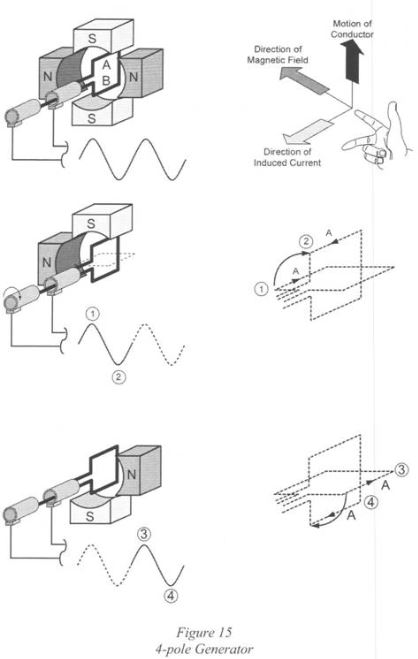
The generation of an alternating EMF is characterized by the direction of current flow in response to the movement of a conductor. When the conductor is shifted from left to right, the current flows in one direction, whereas moving the conductor from right to left causes the current to flow in the opposite direction.
Fleming’s right-hand rule is specifically employed for generators, while the left-hand rule is associated with motors. Both rules serve the purpose of indicating the direction of induced current flow when a conductor interacts with a magnetic field.
Video: Right Hand Rule
Watch “Right Hand Rule” [2:02].
Activity: Right-Hand Rule
Click the arrows to see images of the right-hand rule.
Simple AC Generator
Simple AC generators, also known as alternators, work by rotating a coil of wire within a magnetic field. As the coil spins, it cuts through the magnetic lines of force, inducing an alternating current (AC) in the wire. This AC output is then typically used as a source of electrical power in various applications.
Video: AC Alternator Animation
Watch “AC Alternator Animation” [0:13].
Activity: Simple AC Generator
Click the accordion to learn more about simple AC generators.
Generating an Alternating EMF
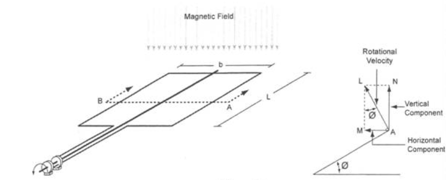
Generating an alternating EMF depends on several factors, including the rotational velocity, the number of magnetic field lines intersected by the loop during rotation, and the strength of the magnetic field.
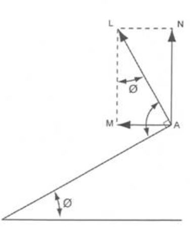
The magnitude of the emf generated in the loop is proportional to the horizontal component – AM. The horizontal component is the component that cuts the magnetic lines of force.
Activity: Generating an Alternating EMF
Click the ticks on the slider to learn more about generating an alternating EMF.
Calculating an Alternating EMF
To calculate the alternating electromotive force generated on one side of the loop, the formula is as follows:
emf = β x L x sin θ x AL volts,
Where:
- L (in meters) represents the length of the conductor within the magnetic field (A).
- β (in teslas) denotes the strength of the magnetic field.
- θ (in degrees) represents the angle of rotation, and
- AL signifies the horizontal component of the rotational velocity, which is equal to sin θ x AL (where v is the velocity in meters per second).
This formula determines the EMF generated in the specified conditions.
Calculating the Total EMF
The total EMF generated across both sides of the loop can be expressed as:
Total EMF = 2 x (β L sin θ AL volts).
Calculating the Maximum EMF
Maximum EMF (Em) occurs when θ = 90°, leading to sin 90° = 1.0.
Therefore,
Em = 2β L v volts,
Where v represents the velocity of the loop.
This formula allows us to determine the maximum EMF under these conditions.
Activity: Calculate the Maximum EMF
Click the arrow to view the solution to the problem.
If the loop is rotated 360° (1 revolution).
The circumference of the circular path taken by the loop is πD (D = diameter of the loop).
D = b, the width of the loop (meters).
If,
- β = Strength of field (T – teslas)
- L = Length of conductor (metres)
- N = Revolutions per minute (r/min)
- b = Width of the loop (metres)
- v (velocity) =


If,
- L = Length of the loop (meters)
- b = width of loop (metres)
- L x b = Area of loop = A
Therefore,
Activity: Calculate the Maximum EMF 2
Click the arrow to view the solution to the problem.
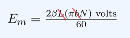
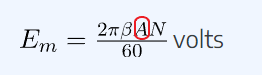
If the loop is formed into several loops (T), the maximum value of emf generated in the coil is:
![\Large \[E_m=\frac{2\pi BATN}{60}\ \text{volts}\]](https://ecampusontario.pressbooks.pub/app/uploads/quicklatex/quicklatex.com-a6d0829f9e94e55be63757f500a1d33d_l3.png "Rendered by QuickLaTeX.com")
Calculating Instantaneous EMF
If the strength of the magnetic field and the rotational velocity remain constant, the generated instantaneous emf is proportional to sin θ. As the coil is rotated in the magnetic field, the value of instantaneous emf is:

Activity: Calculating Instantaneous EMF
Click the tick marks on the slider bar to learn more about calculating instantaneous EMF.
A simple generator has a north and a south pole, or in other words, 2 poles or 1 pole pair.
Calculating Frequency:
Frequency (Hz) x 60 sec/min = Revolutions per min.
Frequency (Hz) = Revolutions per minute/60 sec/min
i.e., To produce 60 Hz power, the loop is rotated at:
- 60 Hz x 60 sec/minute = x r/min
- 60 cycles/sec x 60 sec/minute = 3600 revolutions per minute (r/min)ype your textbox content here.
Calculating Period:
(1) 
i.e., What is the period in 60 Hz power:
(2) 
Activity: Generating an Alternating EMF
Click the arrows to see the solution to this equation.
Frequency, Speed, and Number of Poles
A relationship exists between frequency, speed (r/min), and the number of pole pairs.
If a machine has p pole pairs and if the speed of rotation of the conductor coil is N r/min, the frequency of the generated voltage is:
Frequency,
![\Large \[f = \frac{N p}{60}\]](https://ecampusontario.pressbooks.pub/app/uploads/quicklatex/quicklatex.com-576af6e3eaad61c73b90c63ecb6c0ebc_l3.png "Rendered by QuickLaTeX.com")
To generate 50 Hz power with a 4-pole generator the speed of the conductor loop would have to be:
f = 50 Hz
p = 4 poles/2 = 2 pole pairs
Frequency,
