Planck’s Constant
Experimental Apparatus
The Planck’s constant apparatus is shown in Figure 2.
3.1 Mercury Lamp
CAUTION! The mercury lamp emits UV light, which can damage your eyes with sufficient exposure. Wear your safety goggles if you are looking at or adjusting the apparatus. You can walk with a wooden leg, you can eat with false teeth, but you can’t see with a glass eye.
The mercury lamp is a gas discharge lamp that uses an electric arc through vaporized mercury to produce light. The spectrum of mercury is shown in Figure 3. The filter wheel is used to pick out the wavelengths listed in Table 1.
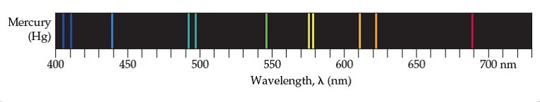
Figure 3: Emission spectrum of mercury
See Section 4.2 for instructions on the proper use of the mercury lamp
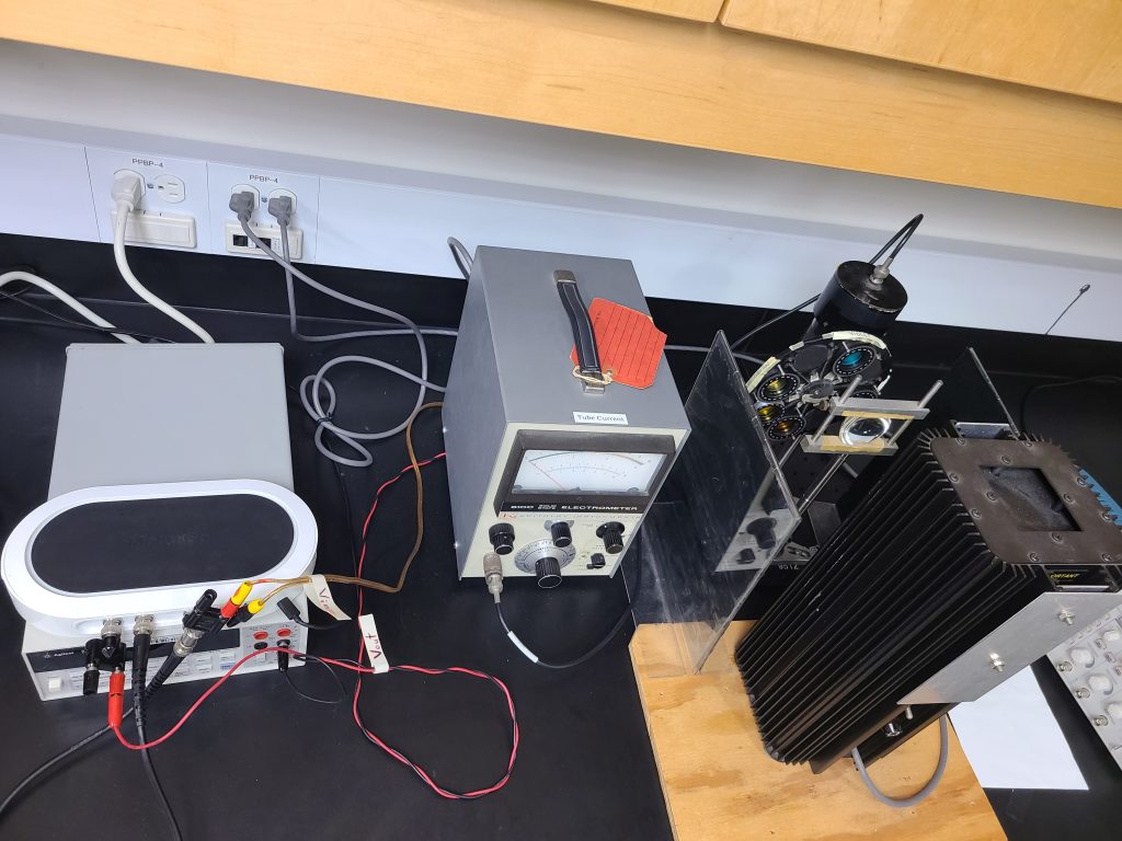
Figure 2: The experiment electronics are shown on the left; the light source, optics, and detector are shown on the right.
|
filter colour |
wavelength (nm) |
|
yellow |
577.0 |
|
green |
546.1 |
|
blue-green |
491.6 |
|
blue |
435.8 |
|
violet |
404.7 |
Table 1: Filter options
3.2 Photocell
The photocell is shown schematically in Figure 1. The anode can be biased relative to the cathode to prevent photoelectrons from leaving the surface of the cathode. In your apparatus, the cathode is made of potassium ( = 2.3 eV) and the anode is made of platinum ( = 6.35 eV). The anode and cathode are kept in a vacuum chamber; otherwise, the photoelectrons would lose their kinetic energy in collisions with gas molecules, and we would not be able to probe their energy with a retarding potential.
3.3 Electrometer
An electrometer is a lot like a digital multimeter in that it can measure input voltage, current or resistance. But an electrometer can measure values much smaller and with much more precision than a typical digital multimeter. In this experiment, the electrometer will be used to measure the current generated by the photoelectrons as they leave the cathode. This current, which is on the order of nano-amps, passes through a specialized vacuum tube that has an incredibly high, yet precisely known, resistance (on the order of 1014 ). The combination of high resistance and low current results in a reasonably-sized voltage that is used to indicate the input current.
3.4 FPGA Data Acquisition System
A Field Programmable Gate Array (FPGA) is, basically, a chip that can be reconfigured over and over again to act as a wide range of hardware, as opposed to being configured when built and being restricted to a single function. The FPGA used in this experiment (MOKU:GO) can be configured to work as an oscilloscope, function generator, spectrum analyzer, lock-in amplifier, and many more instruments. This experiment uses the oscilloscope and function generator functions, which can be used simultaneously.
The FPGA connects to the PC via USB. The Moku app is used to connect to the FPGA, choose the instrument you would like to use, and see that instruments display. The output from the moku:go will provide the retarding voltage to the anode and measure the voltage from the electrometer that indicates the photoelectron current.