Speed of Sound
Experimental Apparatus
The apparatus (shown in Figure 1) consists of two separate arrangements. The first is the cylindrical resonator which is built-up from metal tube sections. The length of each section can be measured with a caliper to find the total length. The speaker at the left side of the tube is driven from the computer’s sound card headphone output. The microphone, located the right end of the tube, is connected to the amplifier unit and connected to the computer’s microphone input. By scanning through a range of input frequencies the location of resonances in the cylindrical tube can be found and the speed of sound can be calculated.
The second portion of the experiment uses a spherical resonator cavity of radius  inches. The speaker and microphone connections are exchanged to connect the spherical resonator. To investigate the effect of the temperature on the speed of sound, the bottom half of the resonator is wrapped with heater-tape which is powered through a variable auto-transformer, a.k.a a variac. The temperature is measured by a thermocouple that is connected to the top half of the resonator.
To investigate the speed of sound in various gases, a small tube is attached to the resonator. Please ask for assistance in turning on the gas cylinders. A small throttling valve is provided at the side of the bench to adjust the gas flow into the resonant cavity. If the gas flow is too low, the air inside the cavity may not be fully displaced. If the gas flow is set too high there may be excessive noise from the gas flow measured by the microphone.
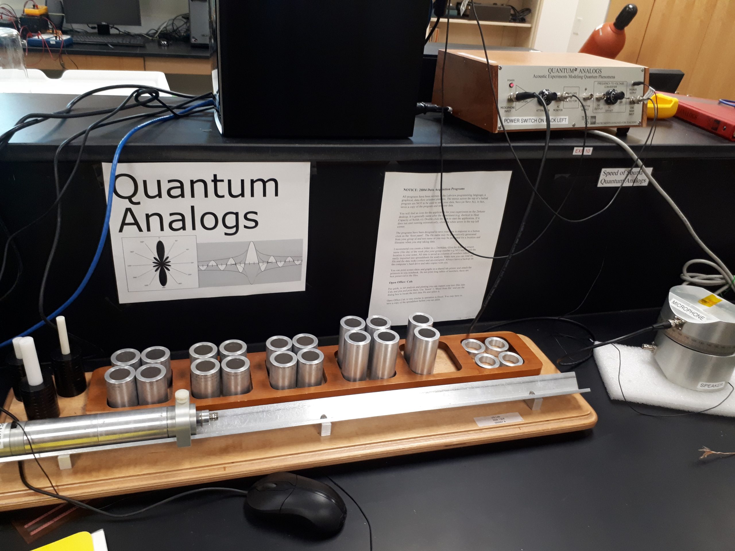
Figure 1: Speed of Sound (A.K.A Quantum Analogs) apparatus. Note the cylinder on the left, the sphere on the right, and the control box and PC at the top of the photo.
The frequency response is measured using the Spectrum SLC software, shown in Figure 2. The software is started by the desktop shortcut. Up to four spectra can be viewed/compared simultaneously on the screen be selecting Spectrum 1-4 before conducting the next measurement. The start frequency should be kept above 100 Hz for all measurements to protect the sound card. The step-size between each measurement is entered and a dwell time for each measurement is set, which can be kept at 50 ms for most measurements. As always, it may be a good idea to do a rough scan with a large step size to get an idea of the general shape of the spectrum and to double check that your settings are reasonable before going through again using a smaller step size to get a high-resolution scan.