3.1.2 – SN2 Mechanisms
SN2 Reaction Mechanism
An SN2 reaction is a nucleophilic substitution reaction that occurs in a single step with both bond breaking and bond forming happening simultaneously. In this type of reaction, an electrophile bound to a good leaving group is attacked by a nucleophile, and the bond to the leaving group dissociates from the molecule just as a bond to the nucleophile is formed. This forms the final products.
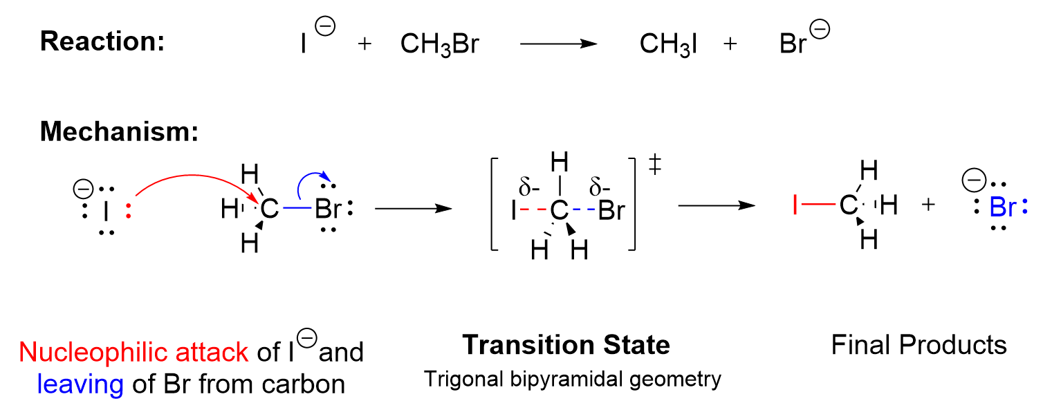
The mechanism is said to be concerted , as one bond is breaking and another is forming simultaneously. The nucleophile donates a pair of electrons to attack the carbon center (Figure 3.1.2.a., red arrow), as the leaving group takes a pair of electrons and dissociates from the carbon center (Figure 3.1.2.a., blue arrow). In the example above, the nucleophile (I–) approaches the electrophilic carbon 180o from the leaving group Br. As the nucleophile I– approaches, the C–Br bond begins to weaken and break. The C–I bond forming event and the C–Br bond breaking event occur simultaneously. For a transient moment (~0.1 picoseconds at room temperature), the transition state has a carbon atom that is partially connected to both I– and Br, which is depicted by the dotted lines. This is the highest energy level state of the whole process. In the transition state of an SN2 reaction, the carbon is pentavalent in nature in a trigonal bipyramidal geometry, with two of the groups only partially bonded. As the I– continues to approach the carbon, the Br further dissociates, taking both electrons in the old C–Br bond. Eventually, the new bond between C and I is completely formed and the old bond between C and Br is fully broken, which gives the product CH3I and the anionic leaving group Br–.
Notes for drawing an SN2 mechanism:
- Two arrows must be shown when drawing the SN2 mechanism to indicate the proper flow of electrons. The first curved arrow points from the nucleophile towards to the electrophilic carbon that it is attacking to demonstrate the electron flow in bond formation. The second curved arrow points from the bond between the carbon and the leaving group towards the leaving group itself as it dissociates to demonstrate electron flow in bond breaking.
- When drawing the transition state, ensure that the nucleophile and leaving group are connected to the center carbon by dotted lines, as these bonds are in the process of forming or breaking respectively. The nucleophile and leaving group are oriented 180° to one another. The entire molecule is enclosed in square brackets with the double dagger symbol on the top right to indicate that it is the transition state.
Because the reaction proceeds in a single step that involves both the nucleophile and the alkyl halide electrophile, increasing the concentration of either species will increase the possibility of a collision occurring between the two. Thus, the SN2 reaction follows second-order kinetics, and the rate law can be written as:
Rate = kobs[Alkyl Halide][Nucleophile].
Due to this, the reaction name SN2 stands for: substitution, nucleophilic, and bimolecular, as two molecules influence the rate of reaction.
(The full solution to this problem can be found in Chapter 5.2)
Energy Diagram of the SN2 Mechanism
The energy profile for the above reaction can be represented in Figure 3.1.2.b. As an SN2 reaction happens in a single step, the diagram has only a single maximum, which is the point of the high energy transition state. This peak represents the overall activation energy for the entire process. The reactants are indicated on the left side and the products are shown on the right.
![An energy profile diagram is drawn where there is an x-axis labeled reaction progress and a y-axis labeled potential energy. Additionally, the graph is labelled Rate = kobs [CH3Br][I-]. There is a red bell-shaped curve where the last point ends higher than the starting point. There’s a vertical line drawn from the lowest to the highest point of the curve and labelled Ea for activation energy. Underneath the starting point an iodide (I-) has an arrow tail from one of its lone pairs with the arrowhead pointing towards the carbon of bromomethane and the bond between carbon and bromine is broken, depicted by curved arrows. The highest point is labelled T.S for transition state and in square brackets bromomethane is drawn using the spatial model where I and Br are both attached to C with dotted lines, including symbols for partially negative on either halogen. The final point of the curve is iodomethane and bromide (Br-).](https://ecampusontario.pressbooks.pub/app/uploads/sites/3169/2023/03/3.1.2.-Energy-Profile-Diagram-for-SN2.png)
The maximum on the curve corresponds to the transition state, which is the highest-energy structure involved in the reaction. A transition state always involves partial bonds; either partially formed bonds or partially broken bonds or both, which results in a molecule that is high in energy and unstable. As a transient species, the transition state can never be isolated, and its structure cannot be determined using experimental techniques. Instead, the structure of the transition state is proposed based on the process taking place, and can be predicted using computational techniques.
The Effect of Alkyl Halide Structure on SN2 the Reaction Rate
Thus far, discussions of the SN2 mechanism have focused on the reaction of bromomethane (CH3Br) with a nucleophile. However, other alkyl halides can also undergo SN2 reactions as well. Studies of the reaction rates for SN2 reactions indicate that the structure of the electrophilic carbon in the alkyl halide dramatically influences the reaction rate (Table 3.1.2.).
| Type of Alkyl Halide | Alkyl Halide Structure | Relative Rate |
| Methyl | CH3X | 30 |
| Primary (1o) | R-CH2X | 1 |
| Secondary (2o) | 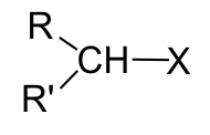 |
0.03 |
| Tertiary (3o) | 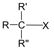 |
Negligible (no SN2 reaction observed) |
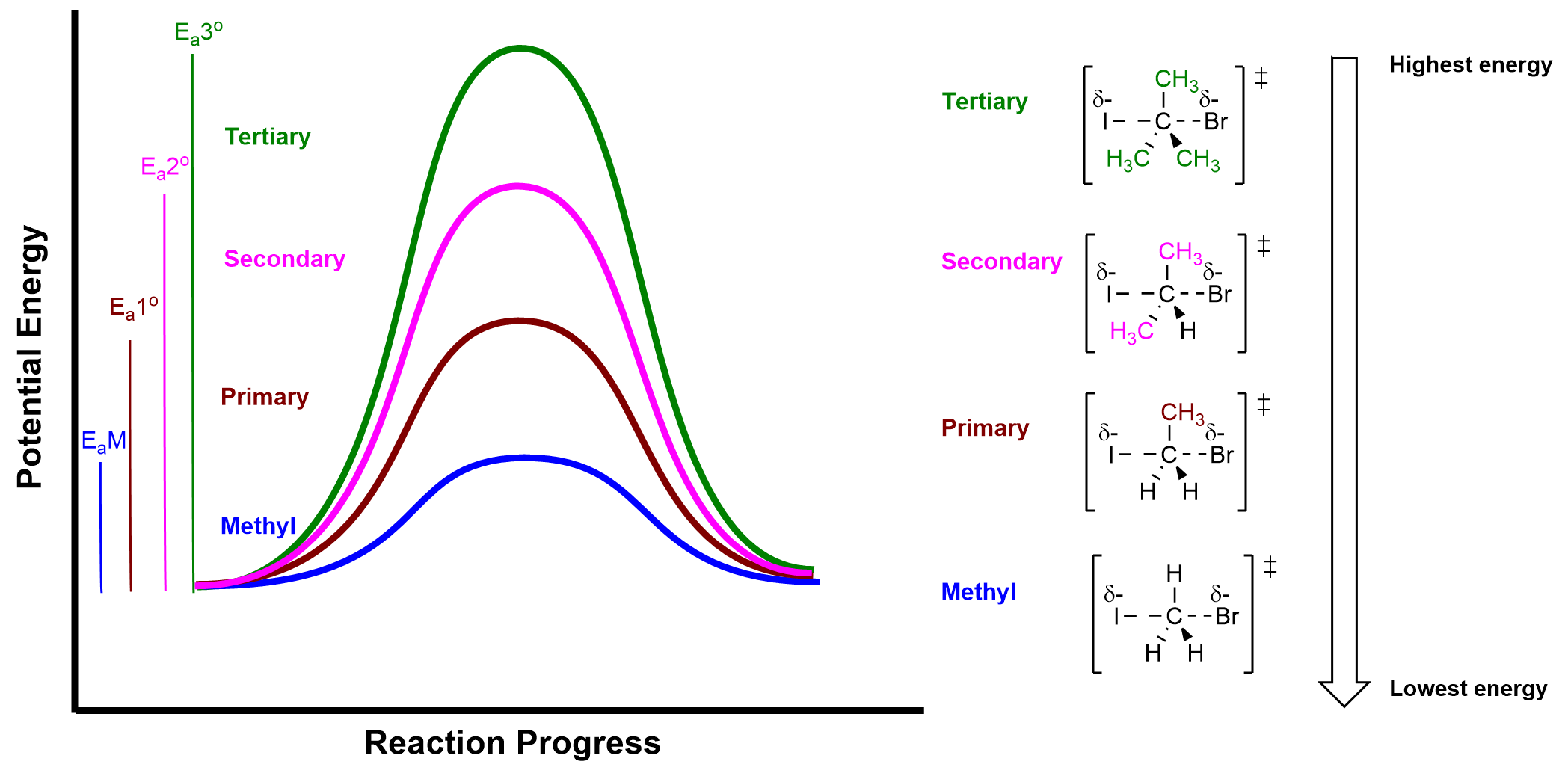
As shown in Table 3.1.2., methyl and primary alkyl halides react the fastest, the rate decreases dramatically for secondary alkyl halides, and tertiary alkyl halides do not undergo an SN2 reaction at all because the rate is too slow to be practically measured. In general, as the number of alkyl substituents increase on the electrophilic carbon, the activation energy for the SN2 reaction increases. A larger activation energy results in a smaller rate constant and a slower rate of reaction. Figure 3.1.2.c.displays how changing the alkyl halide influences the reaction profile diagram and activation energy of the reaction.
The relative reactivity of alkyl halides towards an SN2 reaction can be summarized as:
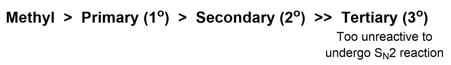
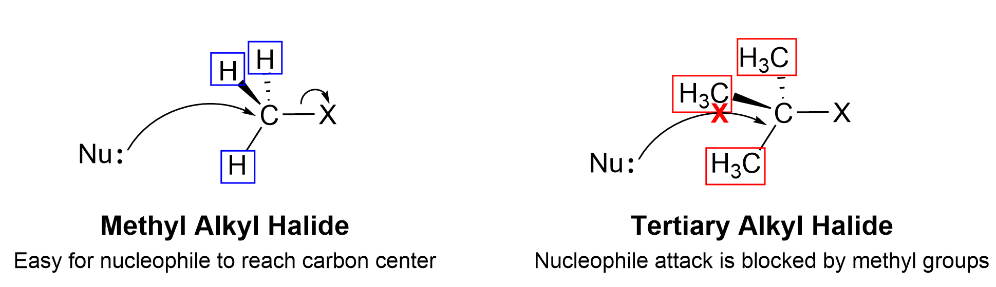
This trend can be explained by the mechanism of the SN2 reaction. When nucleophiles approach the electrophilic carbon, the carbon is still bonded to three other groups as well as the leaving group. For the methyl electrophile, it is easiest for an electron-rich nucleophile to approach the electrophilic carbon because the surrounding hydrogen atoms are small and there is minimal electrostatic repulsion. If the size of the bonded groups becomes larger, it is more difficult for the nucleophile to access the electrophilic carbon as a result of increasing electrostatic repulsion to the neighbouring groups. For tertiary electrophiles, the electrophilic carbon is effectively inaccessible to the incoming nucleophile, as it has three large alkyl groups connected to it.
This reactivity difference is a result of the steric effect . The steric effect describes how the size of the groups (also known as steric bulk) around the electrophile can influence the reaction rate. As the groups around the electrophile become more bulky, steric hinderance increases, making the electrophilic carbon less accessible for nucleophiles to attack. Thus, the SN2 reaction rate of secondary (2°) and tertiary (3°) substrates decreases dramatically. In fact, the 3° substrates almost never undergo SN2 mechanisms because the reaction rate is too slow due to the steric effect, and would prefer to undergo a different type of nucleophilic substitution reaction, the SN1 mechanism, which will be described in Chapter 3.1.3.
Adding Other Functional Groups via SN2 mechanisms
Although the previous section focused on the use of a halide ion as a nucleophile, a variety of other nucleophiles can also be utilized. Hydroxide (OH–), alkoxides (RO–) and carboxylates (RCOO–) can also be used as nucleophiles in SN2 reactions, making it possible to synthesize compounds with a variety of functional groups. For example, the following reaction in Figure 3.1.2.e. can be performed with a primary alkyl halide and a nucleophilic alkoxide, forming an ether product.
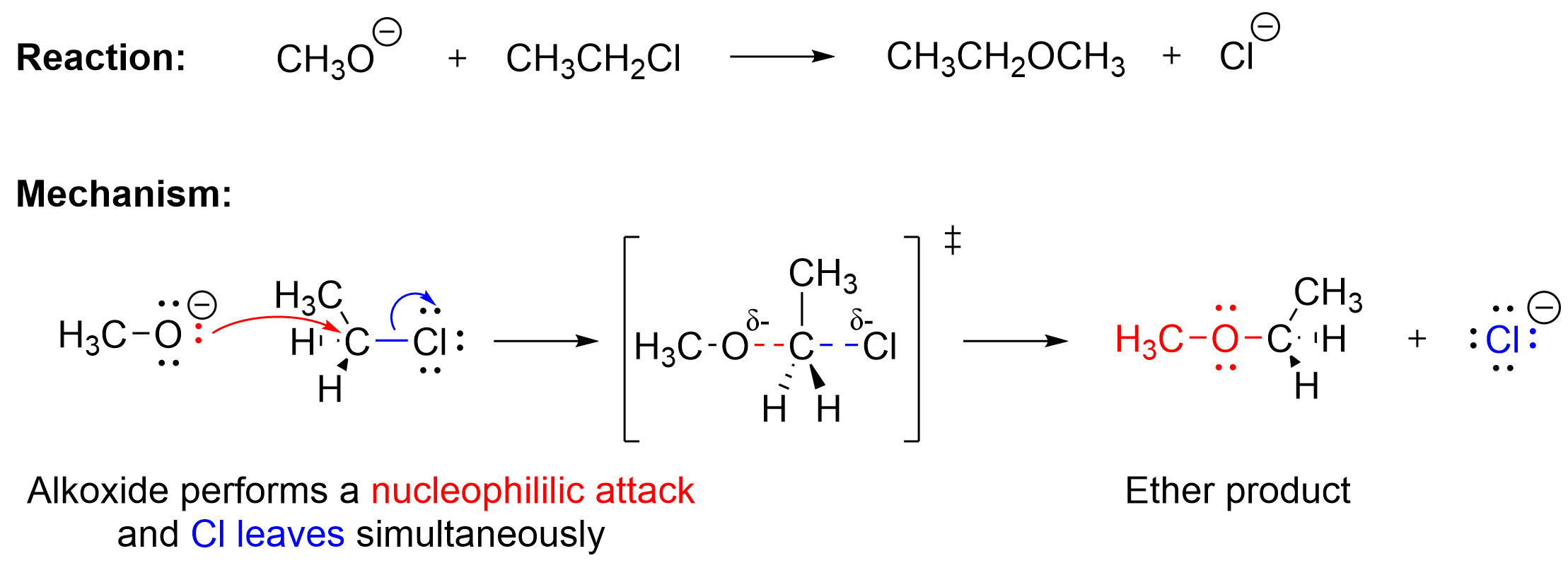
The alkoxide acts as a nucleophile in this reaction, as it is anionic and contains at least one lone pair of electrons that can be used to form a bond, similar to the halide nucleophile discussed in earlier. Thus, the red curved arrow shows the nucleophilic attack of the alkoxide on the electrophilic carbon center, which results in a newly formed C–O bond. Simultaneously, as shown by the blue arrow, the chlorine leaving group takes a pair of electrons and leaves. The arrow represents the movement of the electron pair from the C–Cl bond to the electronegative chlorine, leading to its dissociation. As expected for an SN2 mechanism, the reaction goes through a pentavalent transition state where two partial bonds exist: the C–O bond which is forming, and the C–Cl bond which is breaking. The final products of this process are an ether and a chloride anion.
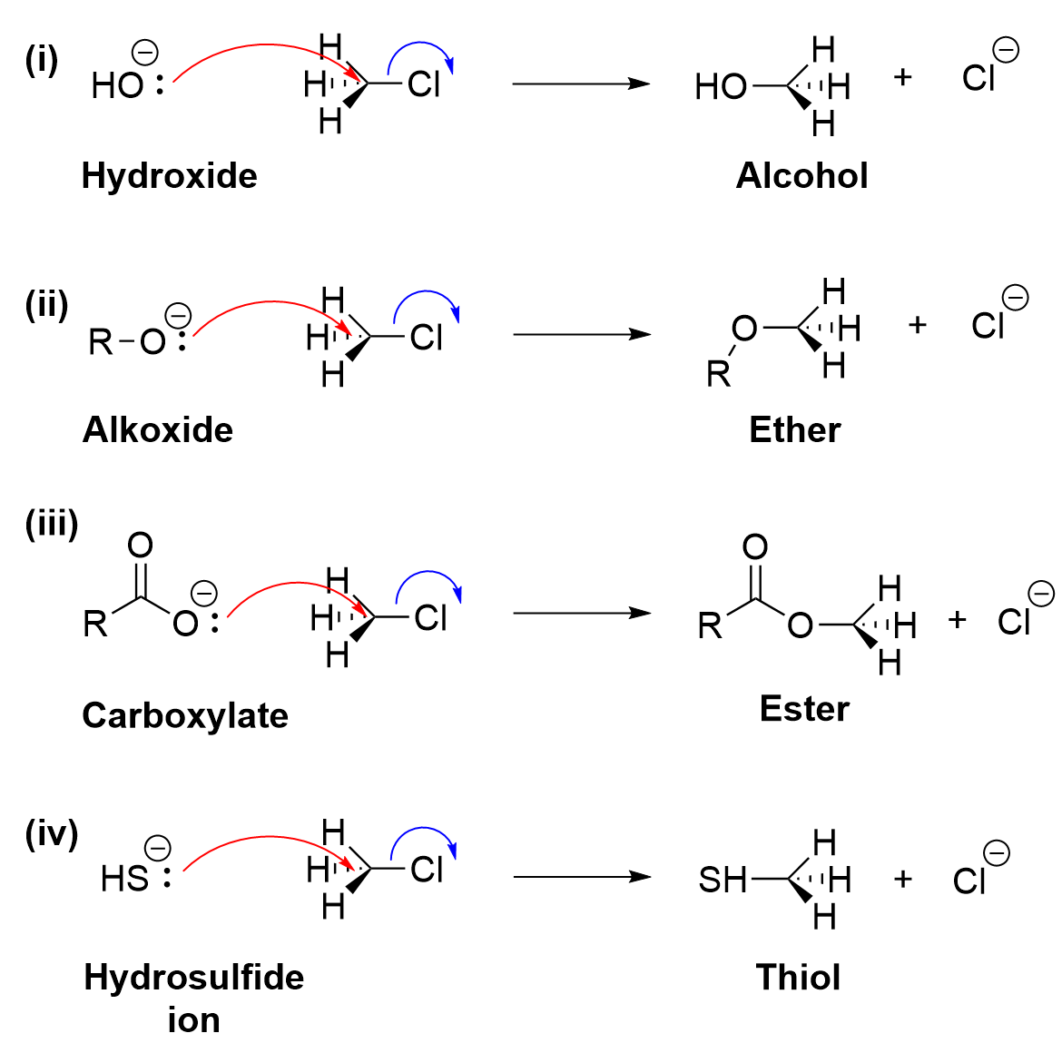
Several oxygen-based nucleophiles can used to build a variety of functional groups onto a compound (Figure 3.1.2.f.). A hydroxide nucleophile can be used to form an alcohol (Figure 3.1.2.f., i), an alkoxide can be used to form an ether (Figure 3.1.2.f., ii), and a carboxylate can be used to form an ester (Figure 3.1.2.f., iii). Note that in each case, the nucleophile is anionic, with oxygen bearing the formal negative charge and acting as the nucleophilic atom. SN2 reactions can also be used to produce thiol products (Figure 3.1.2.f.iv). As sulfur is located directly under oxygen on the periodic table, it has a similar number of valence electrons and reactivity. A hydrosulfide ion (HS–), like hydroxide, contains a lone pair which can be used to attack the electrophilic carbon, forming a new C-S bond and ejecting the chloride as a leaving group.
An Analogy For SN2 Reactions:
Imagine an SN2 reaction as the orchestrated motion of a Newton’s Cradle, where the nucleophile and leaving group play the roles of the swinging spheres. The reaction, like the Cradle, operates in a seamless, single step, without any transitional pause. In this analogy, the electrophile, represented as the stationary spheres throughout the motion, is equipped with a good leaving group, while the nucleophile represents the incoming sphere in motion. As the nucleophile approaches the electrophilic carbon opposite of the leaving group, it initiates a constant backside attack, mirroring the kinetic energy transfer in the Newton’s Cradle. The nucleophile donates a pair of electrons to the carbon center simultaneously as the leaving group dissociates, symbolizing the exchange of energy between the spheres. Unlike the Cradle, however, Sn2 has a partial connection between the carbon/electrophile and leaving group as the nucleophile approaches. The reaction progresses seamlessly, resembling the continuous motion of the spheres in the absence of any pause or hesitation. The concerted nature of the SN2 mechanism, much like the perpetual swing of the Newton’s Cradle, exemplifies the simultaneous breaking of one bond and formation of another, culminating in the creation of the final products.
Key Takeaways
- SN2 stands for substitution nucleophilic bimolecular reaction.
- This reaction occurs in a single, concerted step, with an electrophilic carbon and a nucleophile as reagents.
- This single step involves a transition state which has the electrophilic carbon forming a bond to the nucleophile and breaking a bond to the leaving group.
- Due to the steric effect, only methyl and primary alkyl halides can only be used as effective electrophiles in SN2 reactions.
Key terms in this chapter:
| Key term | Definition |
| Steric Effect | The effect that substituents have on a reaction due to the spatial arrangement of the groups. This plays a large part in determining the rate of SN2 reaction for primary, secondary, and tertiary alkyl halides. More sterically hindered compounds, such as the tertiary alkyl halides, have a larger steric effect resulting in a very slow rate for SN2 reactions. |
Diversity in Chemistry: Maud Menten
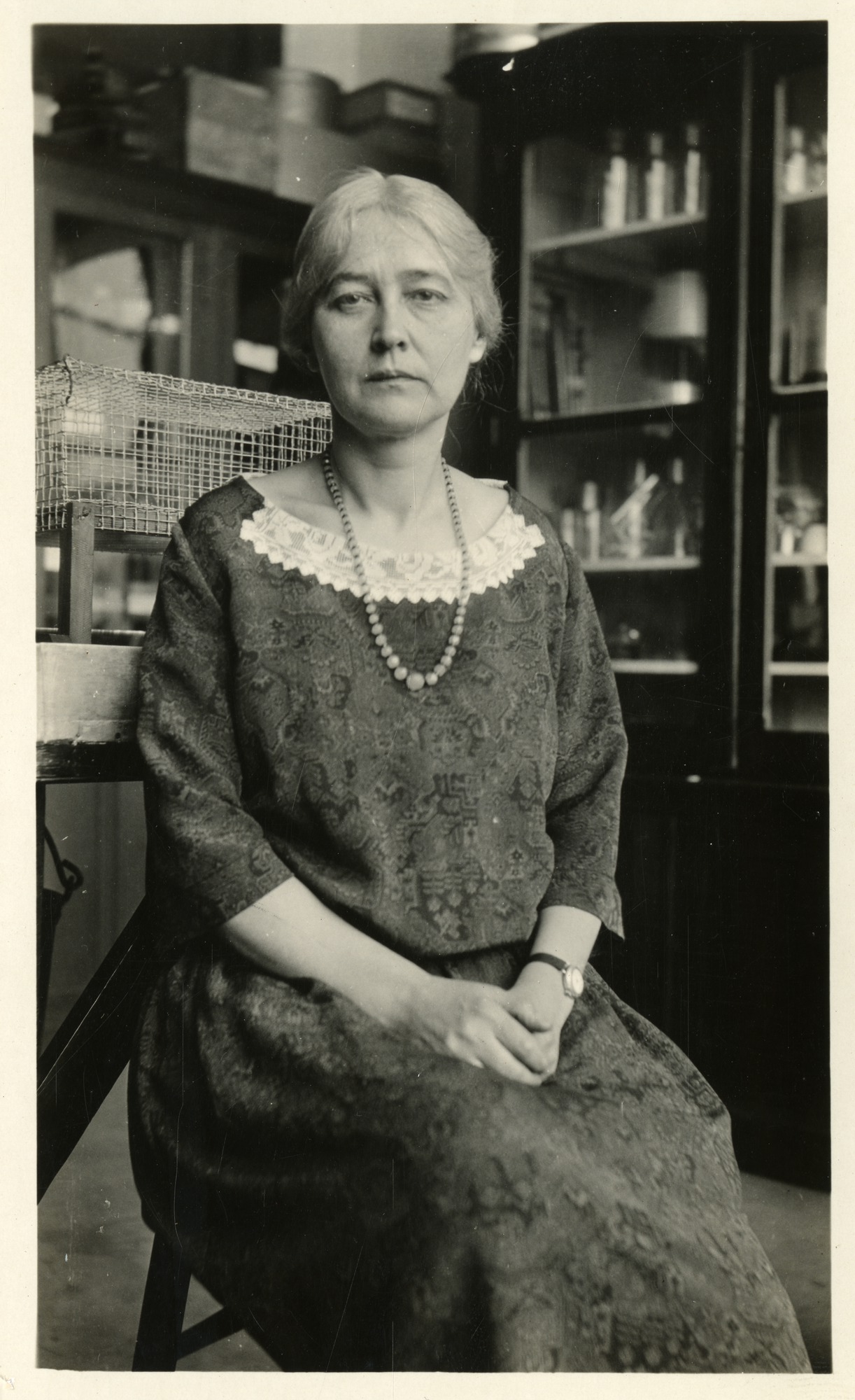 When working with the rate laws of biological reactions, things get a lot more complicated with the introduction of enzyme catalysts. The Michaelis-Menten equation, therefore, is key to understanding simple enzyme kinetics. This equation was in part developed by Maud Menten, a female Canadian physician and chemist. Born in Port Lambton, Menten was one of the first women in Canada to obtain a medical doctorate at the University of Toronto, graduating in 1911. As research opportunities for women were quite scarce during this time period, Menten had to travel abroad in order to pursue her interests. The following year, she moved to Germany in order to work with Leonor Michaelis after becoming interested in his early work on enzyme kinetics. She then went on to publish the Michaelis-Menten equation alongside Michaelis in 1913, before pursuing her Ph.D at the University of Chicago and becoming a professor at University of Pittsburgh until her retirement.
Any feedback or comments on this chapter? You may either email chemoer@mcmaster.ca, access this MS Form, or provide a comment in the feedback box below.
A mechanism where all the bond breaking and forming (all arrows drawn) occur in a single step.
The effect that substituents have on a reaction due to the spatial arrangement of the groups. This plays a large part in determining the rate of SN2 reaction for primary, secondary, and tertiary alkyl halides. More sterically hindered compounds, such as the tertiary alkyl halides, have a larger steric effect resulting in a very slow rate for SN2 reactions.
