4.3 – Electromechanical Relays
Introduction to Electromechanical relays
An electromechanical relay is an electrically-controlled mechanical switch that works by the magnetic attraction of an electromagnet coil acting on an iron armature: energize the coil, and the armature
moves a switch mechanism; de-energize the coil, and the armature falls back to its resting position by the action of a spring. Applications of electromechanical relays abound. One simple application
of a relay is to allow a small electrical signal to control a larger voltage and/or current. A typical relay small enough to fit in the palm of your hand will require less than one Ampere of current to
energize its coil, but the switch contacts of that same relay may be fit to handle many Amperes of current to some load. In this sense, relays may be thought of as discrete amplifiers.
What is a relay?
An electromechanical relay is an electrical switch actuated by an iron armature attracted toward an electromagnet coil. As switching devices, they exhibit simple “on” and “off” behavior with no
intermediate states. Relays are very useful devices, as they allow a single discrete (on/off) electrical signal to control much greater levels of electrical power, and/or multiple power or control signals
that are otherwise isolated from each other. For example, a relay may be controlled by a low-voltage, low-current signal that passes through a delicate switch of some sort (e.g. limit switch, proximity
switch, optical sensor), and then the switching contacts of that relay may be used to control a much higher-voltage, higher-current circuit, and even multiple circuits given multiple sets of switching
contacts. The electronic schematic symbols for two variations of a single-pole, single-throw (SPST) relay are shown here, normally-open (NO) and normally-closed (NC) contact types:
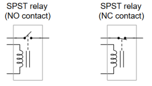
A coil of wire wrapped around a laminated ferrous core provides the magnetic field necessary to actuate the switch mechanism. This electromagnet coil’s actuating influence on the relay’s contact
is represented by the dashed line. The relay on the left-hand side possesses a normally open (NO) switch contact, meaning the switch will be in the open (off) state when the relay coil is in its resting
or de-energized state. The right-hand relay’s switch contact is normally-closed (NC), meaning the switch will be in the closed (on) state when the coil is de-energized. For more information on the
“normal” status of a switch. Complete electrical isolation provided by the relay means the control circuit and power circuit may operate at completely different voltage and current levels, the relay extending the control circuit’s influence to the power circuit without needing to share any electrical points in common.
Contact Arrangements
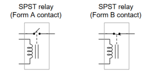
In the electrical control world, the labels “Form-A” and “Form-B” are synonymous with “normally open” and “normally closed” contacts, respectively. Thus, we could have labeled the SPST relay
contacts as “Form-A” and “Form-B,” respectively:
An extension of this theme is the single-pole, double-throw (SPDT) relay contact, otherwise known as a “Form-C” or “changeover” contact. This design of switch provides both a normally-
open and normally-closed contact set in one unit, actuated by the electromagnet coil:
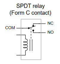
Note the labeling of the switch’s three terminals: “NO” refers to normally-open, “NC” refers to normally-closed, and “COM” means the terminal common to both of those switch contacts. By
now the meanings of the words “pole” and “throw” should be clear too: “pole” refers to the moving portion of a switch contact, while “throw” refers to the stationary portion of a switch contact. A
SPST switch has one moving part and one stationary part. A SPDT switch has one moving part and two different stationary contact points for the moving part to touch.
A further extension on this theme is the double-pole, double-throw (DPDT) relay contact. This design of switch provides two sets of Form-C contacts in one unit, simultaneously actuated by the
electromagnet coil:
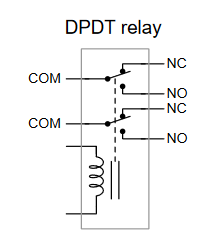
DPDT relays are some of the most common found in industry, due to their versatility. Each Form-C contact set offers a choice of either normally-open or normally-closed contacts, and the two
sets (two “poles”) are electrically isolated from each other so they may be used in different circuits. Relays possessing even more poles are possible, including 3PDT and 4PDT varieties.
Relay Ratings
Electromechanical relays are rated both for their coils as well as for their contacts. Coil ratings are based on the amount of current necessary to reliably actuate the iron armature, while contact
ratings are based on the amount of tolerable arcing while opening and resistive heating while closed.
Relay coils are typically advertised as having a specific voltage, either AC or DC. More detailed
specifications may include pick-up and drop-out voltages (and/or currents), as well as coil resistance. A relay’s pick-up rating is the minimum voltage or current necessary to guarantee the armature will actuate, while the drop-out rating is the maximum voltage or current where the return spring overcomes the coil’s magnetic attraction to return the relay to its resting (or “normal”) state. The
terms “pick-up” and “drop-out” are anachronisms from the days when electromechanical relays used gravity rather than spring tension to return the armature to its resting position: energizing the coil
would literally pick the armature up to actuate the relay’s contacts, and de-energizing the coil would literally drop the armature out of the coil’s center.
Relay contacts, by contrast, are typically advertised with either voltage and current ratings, or voltage and (electric motor) horsepower ratings. The voltage rating is, of course, the maximum
amount of voltage one would expect the contact to bear when open, while the current or horsepower rating refers to the maximum the contact should bear when closed. DC ratings are typically more
conservative than AC ratings, because of DC’s natural tendency to arc. Both coil and contact ratings usually appear on the case of an electromechanical relay, but some interpretation may be necessary. The “12 VDC” rating must refer to the relay’s coil because no current rating accompanies it as would be the case if it referred to a contact rating. The other ratings show grouped current/horsepower/voltage values which means they must be contact ratings. Note that nowhere on this relay’s case does it clearly denote “coil” or “contact” to give context to the ratings – the manufacturer expects the end-user to understand enough about relays to discern one from the other.
Watch
Watch the following video on the basic principles of electromechanical relays:
![]() To learn how to access the transcript for this video, see “YouTube transcript instructions (opens a new window)“
To learn how to access the transcript for this video, see “YouTube transcript instructions (opens a new window)“
Troubleshooting Electromechanical Relays
Electromechanical devices generally fail due to dirty contacts. Remove the relay portion of the EC and gently file away the carbon or other debris that are collected on the contact. Make certain that all of the dust and debris are removed from the electrical contact and the relay coil. After long periods of use, electrical contacts may become worn. It is more cost effective to replace the entire relay than attempt to replace the contact. If the contact is easily accessible and removable, it may be feasible to replace the contact.
Mechanical relays, such as electro-mechanical relays have shorter lifetimes than solid-state relays. The reason for this is that they simply wear out after millions of operations. Solid state relays, on the other hand, have a longer life because there is no mechanical action when they open or close. Even so, electro-mechanical relays are still a very popular choice because they offer lower path resistance and higher operating voltage and operating current.
End-of life failures are the most common type of failure. Using a relay to switch voltages and currents beyond its rated specifications can also cause them to fail.
The troubleshooting process for relays is straight forward:
- Check to ensure that there is voltage to the coil.
- Examine the insulation of the wires that produce the magnetic force. Never attempt to rewind the coil.
- Test the continuity of the solder joints at all terminals.
- Always ensure that plug-in relays are properly seated into the socket.
- Always clean the area around the relay or solenoid to eliminate future problems created by debris preventing full contact.
On all relay data sheets you will find:
Some switching systems include relay operation counters to attempt to predict when a relay will fail. Although it may be helpful to know how intensively a relay is being used, it is not a good indicator on its own. Load conditions alone can impact a relay’s operating life by more than three orders of magnitude.
6 Common issues with relays 1
-
Age of relay/Mechanical wear
- Ingress of particles or water
- Environmental Factors: Heat/Cold
- Power supply error
- Burnt Coil
- Corrosion
What to do?
- All relays come with a typical lifespan, after a defined set of hours of operation or number of switches, relays will fail. Electromechanical relays do not last as long as solid state relays due to their moving parts, you may want to switch out relays for solid state options. If a relay fails due to its age, you simply have to replace the relay with a new one.
- Particles (I.e. dirt, dust, sand etc.) can make their way into the relay. Carefully clean parts and make sure the relay is clean. If necessary/possible, use a filter. For ingression of water, ensure the electrical ratings are suitable for the environment in which you are using the relay and use a higher rated relay if possible. Ensure all enclosures have proper sealing and protection from water. If water does damage the relay, you will have to replace the entire relay.
- Environmental factors: extreme heat and cold can damage relays. Similar to particles, ensure that the relay you are using is designed to be used in your environment. Change the relays to appropriately rated ones if necessary.
- Power supply error: If improper amounts of current or voltage are applied to a relay, it can damage internal components of that relay. Check to ensure a stable amount of current and voltage is being applied to the relay and that those values are within the relays technical specifications. Additionally, you can use protective devices such as fuses to prevent excess power from damaging the component
- Burnt Coil: coils commonly fail for two reasons: excess current or voltage being applied and ingress of particles or water. Common symptoms of a burnt coil are burn marks, cold when powered and infinite resistance. Ensure power supply is correct for the environment you are using it in and coil can ventilate heat. Install new coil if necessary.
- Corrosion: exposure to chemicals (even water vapour or salt, not just disinfectants). Once again, ensure your relay is rated for the environment it is being used in.
Watch
Watch the following video on troubleshooting electromechanical relays:
![]() To learn how to access the transcript for this video, see “YouTube transcript instructions (opens a new window)”
To learn how to access the transcript for this video, see “YouTube transcript instructions (opens a new window)”
Attributions
This chapter is partly adapted from the following:
- Modular Electronics Learning (ModEL) project: Electromechanical Relays by T.R. . Kuphaldt is licensed under CC BY 4.0
References
- Cope, L. (2022). What causes a relay to fail? (And how to avoid it). Engineer Fix.
- Video: Working of electromagnetic relay by DG E LEARING ADU ACADEMY
- Video: How to Test a Relay the Correct Way by Ratchets And Wrenches
