1.3 – Classifying Biomedical Equipment
Classification of Applied Biomedical Equipment
The term ‘applied’ refers to any piece of biomedical equipment that comes in contact with the body. Not all biomedical equipment comes in contact with the body (ex. Laser thermometers used to take temperature during the pandemic). Therefore, not all biomedical equipment is subject to this classification. This classification is important as it will determine the maximum amount of leakage current that device is allowed to have. This is important for you: if you measure the leakage current and it is above the maximum allowable amount, you will have to fix or stop using that device. Applied devices fall into three categories: B (body), BF (body floating), and CF (cardiac floating). B is the least stringent and are typically used for medical devices that attach to body parts that are not conductive or devices that can be immediately released from the patient. BF is used for applied parts that are attached to the patient or have medium to long contact times with patients. CF is the most stringent classification and is used for applied parts that come in contact with the heart.
Table 1.3.1
Health Canada Classification of Biomedical Equipment
| Classification of Applied Equipment | Intended Application | Maximum leakage current (µA) under normal conditions | Maximum leakage current (µA) under a single fault condition | Examples |
|---|---|---|---|---|
| B (‘Body’, grounded) |
Generally not conductive or can immediately be released from patient |
100 | 500 | Phototherapy equipment, Magnetic Resonance Imaging scanners, Hospital beds |
| BF (“Body floating”, not connected to earth) | Conductive equipment – medium/long applications | 100 | 500 | Ultrasound equipment, blood pressure monitors and incubators |
| CF (“Cardiac Floating”, separated from earth) | Equipment with cardiac applied parts | 10 | 50 | Defibrillators, Dialysis machines |
Different countries have different classification systems for their biomedical devices. As you can see below, Health Canada (HC) uses four categories while the FDA (USA) and European Council Directive use only three categories.
Table 1.3.2
Health Canada medical device classification table rating showing the four different classes of biomedical instrumentation, the risk level and examples of each class
| Medical Device Classification System | ||
|---|---|---|
| Canadian Classification of Biomedical Equipment | Risk Level | Examples |
| Class I | Lowest | Band-aids/bandages, Toothbrush |
| Class II | Low | TENS machines, epidural catheters, Pregnancy tests |
| Class III | Moderate | Dialysis machines, Hip/knee/breast implants |
| Class IV | High | Pacemakers, Cardiovascular stent |
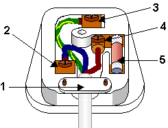
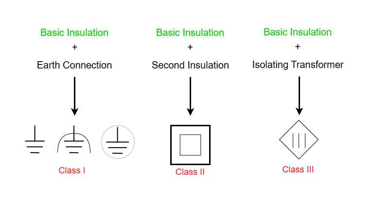
Class I devices (HC, FDA and ECD) that have an electronic component are usually made of metal, have 3 cables (live, neutral and earth), have a metal earth pin and have a fuse in the plug. There is also basic insulation such as a plastic connector that holds live and neutral wires preventing them from touching the metal case.
Class II and III devices (Roughly equivalent to FDA Class 2 and ECD Class IIa and IIb devices) usually have a plastic cover and has two layers of insulation: a basic insulation (plastic cover) and a plastic casing. This double insulation removes he need for an earth connection.

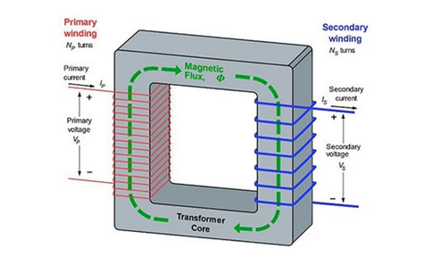
Class IV devices (FDA and ECD Class III devices) use an isolating transformer that have two separate coil windings: a primary winding that is connected to power source and a secondary winding that is connected to appliance. There is no need for a ground. Magnetic flux is produced by the primary winding (red). Magnetic flux is contained in the transformer core which links it to the secondary winding (blue). The magnitude of the induced voltage in the secondary winding is determined by the ratio of turns between the primary and secondary winding.
Applied and other symbols on medical devices
Color codes for electrical power cables
A note on insulation color-coding: Insulating plastic is color-coded to identify live/hot, neutral and ground wires but these codes vary around the world. Live/hot wires may be brown, red, black, blue or grey. Neutral wire may be blue, black or white. Since the same color may be used for live/hot or neutral in different parts of the world, it is essential to determine the color code in your region. The only exception is the earth/ground wire which is often green but may be yellow or just bare wire. Striped coatings are sometimes used for the benefit of those who are colorblind.

Canada AC power circuit wiring colour codes
Table 1.3.3
Electrical wire function and its common label and colour in Canada
| Wire Function | Label | Common Colour |
|---|---|---|
| Protective ground | PG | green or green-yellow |
| Neutral | N | white |
| Line, single phase | L | black or red (2nd hot) |
| Line, 3-phase | L1 | red |
| Line, 3-phase | L2 | black |
| Line, 3-phase | L3 | blue |
US AC power circuit wiring colour codes
Table 1.3.4
Electrical wire function, its label and common/alternative colours in the United States of America
| Wire Function | Label | Common Colour |
Alternative Colour |
|---|---|---|---|
| Protective ground | PG | bare, green, or green-yellow | green |
| Neutral | N | white | grey |
| Line, single phase | L | black or red (2nd hot) | |
| Line, 3-phase | L1 | black | brown |
| Line, 3-phase | L2 | red | orange |
| Line, 3-phase | L3 | blue | yellow |
The three-wire system replaced the older two-wire system, which lacks an earth/ground wire. Under ordinary circumstances, insulation on the live/hot and neutral wires prevents the case from being directly in the circuit, so that the earth/ground wire may seem like double protection. Grounding the case solves more than one problem, however. The simplest problem is worn insulation on the live/hot wire that allows it to contact the case, as shown in Figure 1.3.6. Lacking an earth/ground connection (some people cut the third prong off the plug because they only have outdated two hole receptacles), a severe shock is possible. This is particularly dangerous in the wet parts of the hospital, where a good connection to earth/ground is available through water on the floor, a water faucet or bodily fluids. With the earth/ground connection intact, the circuit breaker will trip, forcing repair of the appliance. Why are some appliances still sold with two-prong plugs? These have nonconducting cases, such as power tools with impact resistant plastic cases, and are called doubly insulated. Modern two-prong plugs can be inserted into the asymmetric standard outlet in only one way, to ensure proper connection of live/hot and neutral wires.

Hospital Grade Power Cords and Green Dot Medical Power Cords
Power cords used in hospital environments are subject to special requirements by Underwriters Laboratories. Before granting approval, UL applies rigorous tests which check durability and conductivity to ensure that the product operates at peak levels. Once a product line is approved, it is stamped with the green dot which is the trademark of hospital grade UL cords. That is why Medical Power Cords are often referred to as Green Dot Hospital Grade Power Cords. Hospital grade cords and cord sets have solid pins, larger plug bodies which virtually eliminate the risk of wire to outer contour shock, and withstand greater pull forces.
Hospital Grade Power Cords are divided for your convenience into three categories:
- Cords with one end: feature exposed wire on the opposite end making them ideal for hard-wiring into appliances.
- Cords with two ends: are used when the application you are powering has a built-in inlet for the connection.
- Multi-leg cords: feature a splitter that supports two or more receptacles.
Attributions
Unless otherwise noted, the content of this chapter is adapted from “23.8. Electrical Safety: Systems and Devices” College Physics, 1st edition by Paul Peter Uron, Roger Hinrichs, Openstax and is under a Creative Commons Attribution 4.0 International License. Access for free at https://openstax.org/books/college-physics/.
- Figure 1.3.1 Three Pins main plug by Slashme courtesy of Wikimedia Commons. Licensed under CC BY SA 3.0
- Figure 1.3.2 Safety caps – Appliance Class II by Elcap courtesy of Wikimedia Commons. Dedicated to public domain through a CC0 license.
- Figure 1.3.3 Isolating Transformer by BillC courtesy of Wikimedia Commons. Licensed under CC BY SA 3.0
- Figure 1.3.5 Wiring Colour Codes by All About Circuits is licensed under CC BY-SA 4.0

.svg)