2.5 – How to Read Schematics
Schematics are our map to designing, building and troubleshooting circuits. Understanding how to read and follow schematics is an important skill for any biomedical technologist and engineer. We are going to go over all of the most fundamental of circuit components and symbols and talk about how those symbols are connected on schematics to create a model of a circuit. Although there are likely dozens of different symbols, we are going to only go through the ones you are most likely to encounter with biomedical equipment.
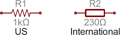
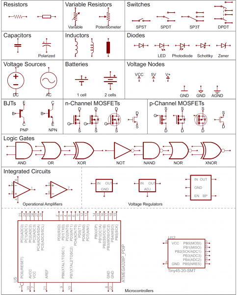
Resistors
Resistors on a schematic are usually represented by a few zig-zag lines, with two terminals extending outward. Schematics using international symbols may instead use a featureless rectangle, instead of the squiggles.
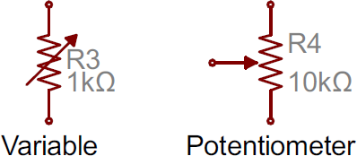
Potentiometers and Variable Resistors
Variable resistors and potentiometers each augment the standard resistor symbol with an arrow. The variable resistor remains a two-terminal device, so the arrow is just laid diagonally across the middle. A potentiometer is a three-terminal device, so the arrow becomes the third terminal (the wiper).
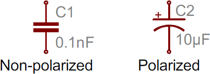
Capacitors
There are two commonly used capacitor symbols. One symbol represents a polarized (usually electrolytic or tantalum) capacitor, and the other is for non-polarized caps. In each case there are two terminals, running perpendicularly into plates. The symbol with one curved plate indicates that the capacitor is polarized. The curved plate represents the cathode of the capacitor, which should be at a lower voltage than the positive, anode pin. A plus sign might also be added to the positive pin of the polarized capacitor symbol.
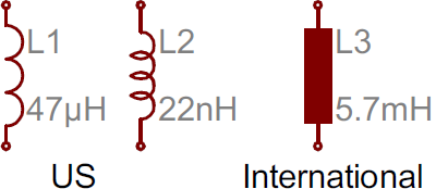
Inductors
Inductors are usually represented by either a series of curved bumps, or loopy coils. International symbols may just define an inductor as a filled-in rectangle.
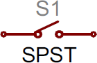
Switches
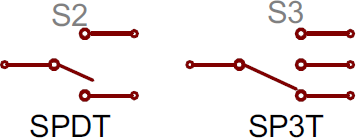
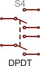
Switches exist in many different forms. The most basic switch, a single-pole/single-throw (SPST), is two terminals with a half-connected line representing the actuator (the part that connect the terminals together). Switches with more than one throw, like the Single-pole/double throw (SPDT) and SP3T below, add more landing spots for the actuator. Switches with multiple poles, usually have multiple, alike switches with a dotted line intersecting the middle actuator (DPDT).
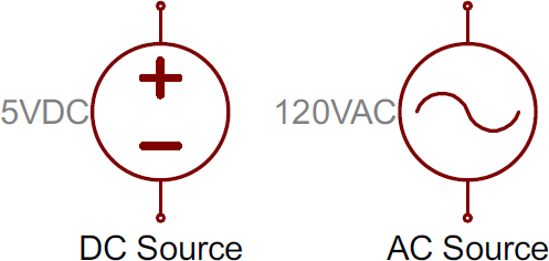
Power Sources
There are a wide variety of power source circuit symbols for DC or AC Voltage Sources. Most of the time when working with electronics, you’ll be using constant voltage sources. We can use either of these two symbols to define whether the source is supplying direct current (DC) or alternating current (AC):
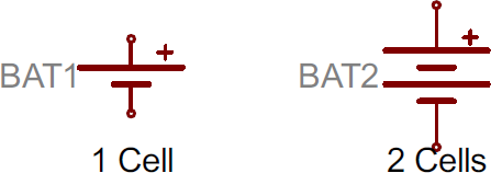
Batteries
Batteries, whether they’re those cylindrical, alkaline AA’s or rechargeable lithium-polymers, usually look like a pair of disproportionate, parallel lines. More pairs of lines usually indicates more series cells in the battery. Also, the longer line is usually used to represent the positive terminal, while the shorter line connects to the negative terminal.
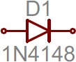
Diodes
Basic diodes are usually represented with a triangle pressed up against a line. Diodes are also polarized, so each of the two terminals require distinguishing identifiers. The positive, anode the terminal running into the flat edge of the triangle. The negative, cathode extends out of the line in the symbol.
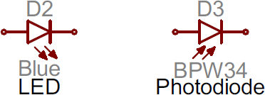
There are all sorts of different types of diodes, each of which has a special riff on the standard diode symbol. Light-emitting diodes (LEDs) augment the diode symbol with a couple lines pointing away. Photodiodes, which generate energy from light (basically, tiny solar cells), flip the arrows around and point them toward the diode.
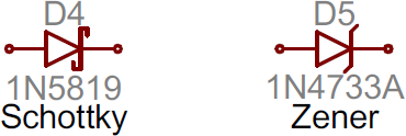
Other special types of diodes, like Schottky’s or zeners, have their own symbols, with slight variations on the bar part of the symbol.
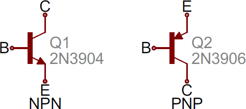
Transistors, BJTs or MOSFETs
Transistors, BJTs or MOSFETs, can exist in two configurations: positively doped, or negatively doped. So for each of these types of transistor, there are at least two ways to draw it. Bipolar Junction Transistors (BJTs). BJTs are three-terminal devices; they have a collector (C), emitter (E), and a base (B). There are two types of BJTs – NPNs and PNPs – and each has its own unique symbol. The collector (C) and emitter (E) pins are both in-line with each other, but the emitter should always have an arrow on it. If the arrow is pointing inward, it’s a PNP, and, if the arrow is pointing outward, it’s an NPN. A mnemonic for remembering which is which is “NPN: not pointing in.”
Metal Oxide Field-Effect Transistors (MOSFETs)
Like BJTs, MOSFETs have three terminals, but this time they’re named source (S), drain (D), and gate (G). And again, there are two different versions of the symbol, depending on whether you’ve got an n-channel or p-channel MOSFET. There are a number of commonly used symbols for each of the MOSFET types.
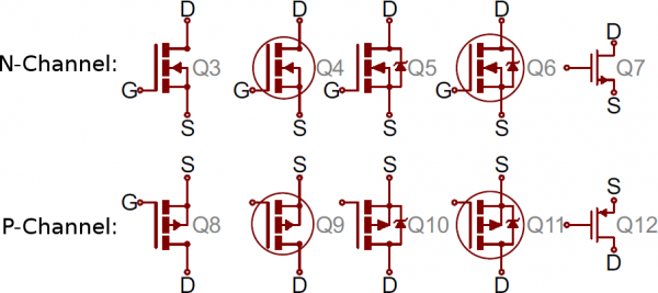
The arrow in the middle of the symbol (called the bulk) defines whether the MOSFET is n-channel or p-channel. If the arrow is pointing in means it’s a n-channel MOSFET, and if it’s pointing out it’s a p-channel. Remember: “n is in” (kind of the opposite of the NPN mnemonic).
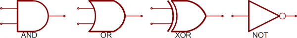
Digital Logic Gates
Our standard logic functions – AND, OR, NOT, and XOR – all have unique schematic symbols:
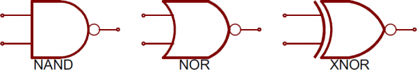
Adding a bubble to the output negates the function, creating NANDs, NORs, and XNORs:
They may have more than two inputs, but the shapes should remain the same (well, maybe a bit bigger), and there should still only be one output.
Integrated Circuits
ICs accomplish such unique tasks, and are so numerous, that they don’t really get a unique circuit symbol. Usually, an integrated circuit is represented by a rectangle, with pins extending out of the sides. Each pin should be labeled with both a number, and a function.
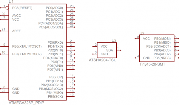
As you can see, these components greatly vary in size and pin-counts. Because ICs have such a generic circuit symbol, the names, values and labels become very important. Each IC should have a value precisely identifying the name of the chip.
Unique ICs: Op Amps, Voltage Regulators
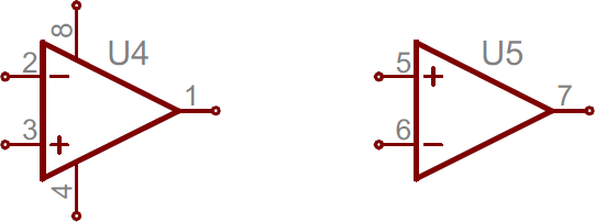
Some of the more common integrated circuits do get a unique circuit symbol. You’ll usually see operation amplifiers laid out like below, with 5 total terminals: a non-inverting input (+), inverting input (-), output, and two power inputs. Often, there will be two op amps built into one IC package requiring only one pin for power and one for ground, which is why the one on the right only has three pins.
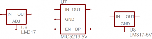
Simple voltage regulators are usually three-terminal components with input, output and ground (or adjust) pins. These usually take the shape of a rectangle with pins on the left (input), right (output) and bottom (ground/adjust).
Crystals or resonators
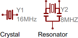
Are usually a critical part of microcontroller circuits. They help provide a clock signal. Crystal symbols usually have two terminals, while resonators, which add two capacitors to the crystal, usually have three terminals.
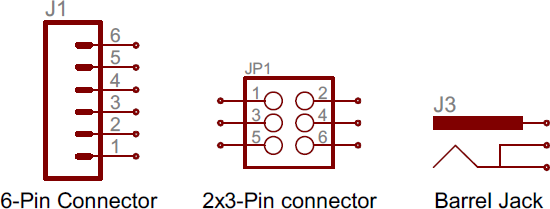
Headers and Connectors
Whether it’s for providing power, or sending out information, connectors are a requirement on most circuits. These symbols vary depending on what the connector looks like, here’s a sampling:
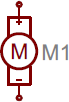
Motors, Transformers, Speakers, and Relays
Motors generally involve an encircled “M”, sometimes with a bit more embellishment around the terminals:
Transformers usually involve two coils, butted up against each other, with one or a couple of lines separating them.
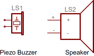
Speakers and buzzers usually take a form similar to their real-life counterpart.
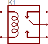
Relays usually pair a coil with a switch.
Fuses and PTCs
Are devices which are generally used to limit large inrushes of current – each have their own unique symbol:
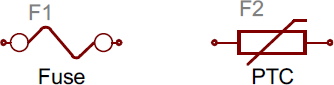
The PTC symbol is actually the generic symbol for thermistor, a temperature-dependent resistor.
Summary
One of the biggest keys to being schematic-literate is being able to recognize which components are which. The component symbols tell half the story, but each symbol should be paired with both a name and value to complete it.
Values help define exactly what a component is. For schematic components like resistors, capacitors, and inductors the value tells us how many ohms, farads or henries they have. For other components, like integrated circuits, the value may just be the name of the chip. Crystals might list their oscillating frequency as their value. Basically, the value of a schematic component calls out its most important characteristic.
Component names are usually a combination of one or two letters and a number. The letter part of the name identifies the type of component – R’s for resistors, C’s for capacitors, U’s for integrated circuits, etc. Each component name on a schematic should be unique; if you have multiple resistors in a circuit, for example, they should be named R1, R2, R3, etc. Component names help us reference specific points in schematics.
The prefixes of names are pretty well standardized. For some components, like resistors, the prefix is just the first letter of the component. Other name prefixes are not so literal; inductors, for example, are L’s (because current has already taken I ). Here’s a quick table of common components and their name prefixes:
Although theses are the “standardized” names for component symbols, they’re not universally followed. You might see integrated circuits prefixed with IC instead of U, for example, or crystals labeled as XTAL’s instead of Y’s. Use your best judgment in diagnosing which part is which. The symbol should usually convey enough information.
Table 2.5.1
A list of common components found in biomedical equipment and their associated name identifiers
| Name Identifier | Component |
|---|---|
| R | Resistors |
| C | Capacitors |
| L | Inductors |
| S | Switches |
| D | Diodes |
| Q | Transistors |
| U | Integrated Circuits |
| Y | Crystals and Oscillators |
Schematic Reading Tips
Identify Blocks
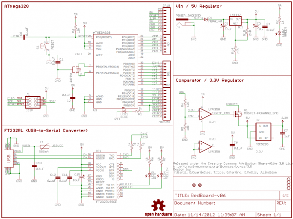
Truly expansive schematics should be split into functional blocks. There might be a section for power input and voltage regulation, or a microcontroller section, or a section devoted to connectors. Try recognizing which sections are which, and following the flow of circuit from input to output. Really good schematic designers might even lay the circuit out like a book, inputs on the left side, outputs on the right.
Recognize Voltage Nodes
Voltage nodes are single-terminal schematic components, which we can connect component terminals to in order to assign them to a specific voltage level. These are a special application of net names, meaning all terminals connected to a like-named voltage node are connected together.
Reference Component Datasheets
If there’s something on a schematic that just doesn’t make sense, try finding a datasheet for the most important component. Usually the component doing the most work on a circuit is an integrated circuit, like a microcontroller or sensor. These are usually the largest component, oft-located at the center of the schematic.
Diagrams
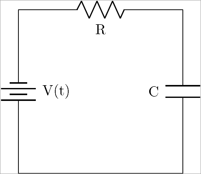
Diagrams are a representation of the different components of a system using abstract, graphic symbols (see above) rather than pictures of the objects. Schematics attempt to make understanding the anatomy of a piece of equipment easier by simplifying the diagram and omitting details that may not be relevant. Below is a schematic of a very simple circuit. Based on the above material we can determine that a 2-cell battery is connected in series with a resistor and a non-polarized capacitor.
There are different types of schematic diagrams that each have ideal functions.
One of the most frequently used diagrams in motor control work is the ladder diagram, also known as a schematic diagram. This diagrams uses symbols to identify components and interconnecting lines to display the electrical continuity of a circuit. Ladder diagrams show how a circuit works logically and electrically. When troubleshooting or designing, we use “ladder” or “schematic” diagrams to represent how the circuit works but these diagrams do not show how equipment is physically laid out, nor do they represent how things are wired “in the real world.” Two components might be right next to each other on the ladder diagram and 50 meters apart in the real world.
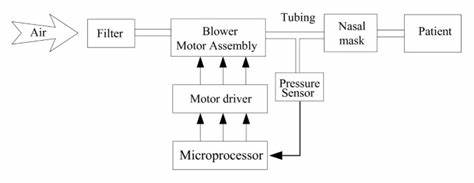
Similar to a schematic diagram, one can use a block diagram. Instead of using symbols a block diagram uses rectangles with the name of the part inside
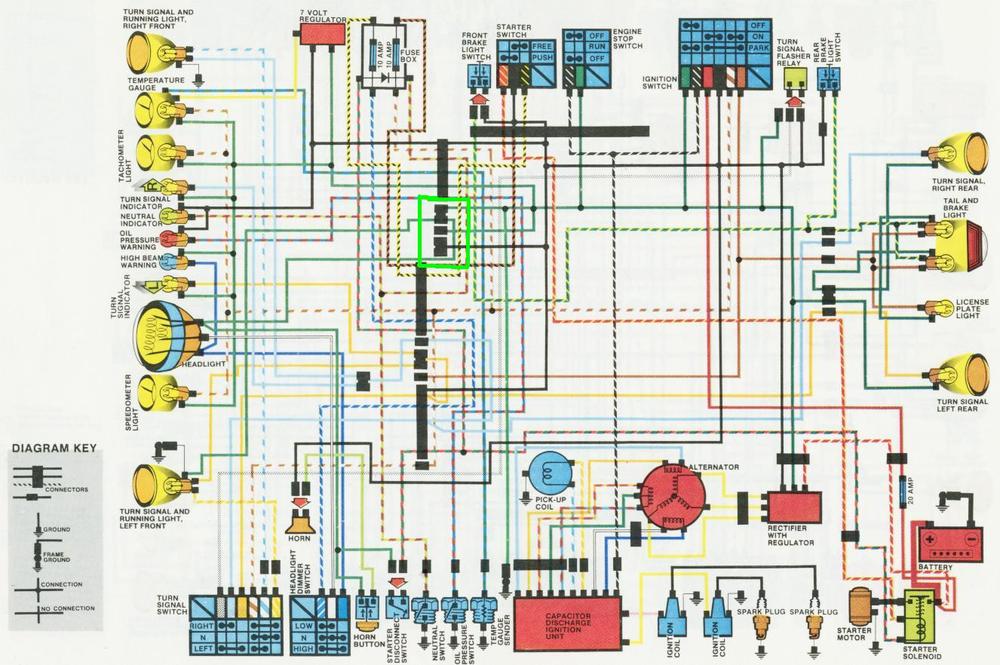
Wiring diagrams, also called connection diagrams, however, do show how equipment is laid out and the connections between them. A wiring diagram shows the relative layout of the components and the wire connections between them. This type of diagram shows the physical relation of all devices in the system, the conductor terminations between these devices, and are commonly used in motor control installations.
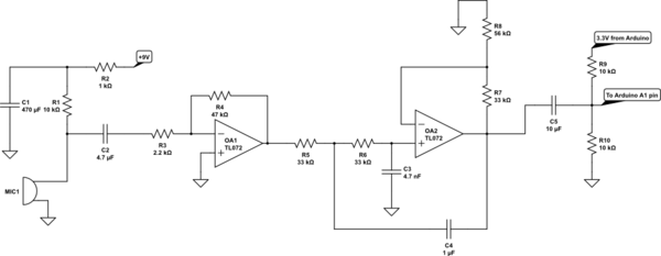
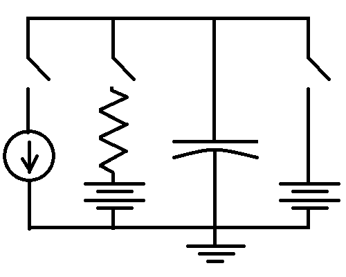
Read the Schematic
Can you describe all of the components of the following schematic and detail how they interact with each other? If you can not, I would suggest taking the time to learn as the schematics you will work with in our labs are going to be more complex.
Attributions
Unless otherwise noted, the content of this chapter is adapted from How to read a schematic by SparkFun is licensed under CC BY-SA 4.0 and from Basic Motor Control by Aaron Lee and Chad Flinn is licensed under a CC BY 4.0
- Figures 2.5.1 2.5.29 How to read a schematic by SparkFun is licensed under CC BY-SA 4.0
- Figure 2.5.30 Simple RC Circuit by GamerMan7799 courtesy of Wikimedia Commons. Licensed under CC BY SA 4.0
- Figure 2.5.31 Simulate this circuit by Sadan Arshad on StackExchange is licensed under CC BY-SA 3.0
- Figure 2.5.32 Chen, ZL., Hu, ZY. & Dai, HD. Control system design for a continuous positive airway pressure ventilator. BioMed Eng OnLine 11, 5 (2012) is licensed under CC BY 2.0 Retrieved from: https://doi.org/10.1186/1475-925X-11-5
- Figure 2.5.33 CX Wiring diagram by MotoVillage is licensed under CC BY 4.0
- Figure 2.5.34 Integrate and fire circuit diagram by David Wallace Croft courtesy of Wikimedia Commons. Dedicated to public domain through CC0 license.
