2.3 – Electrical Safety: Equipment
Biomedical engineering technologists must be able to identify the electrical hazards and control the risks. Safety precautions must be the first priority.
You will need to familiarize yourself with the Canadian Standards Organization as they are responsible for many different aspects of biomedical safety in Canada including:
- Setting minimum standards equipment must meet in Canada
- Generate potential hazards list
- Categorize hazards
- They test and certify electrical products (look on the back of different biomedical equipment to see if it has the CSA branding)
- Training
Safe Circuit Design
Electricity has two hazards. A thermal hazard occurs when there is electrical overheating. A shock hazard occurs when electric current passes through a person. Both hazards have already been discussed. Here we will concentrate on systems and devices that prevent electrical hazards.
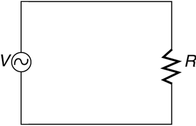
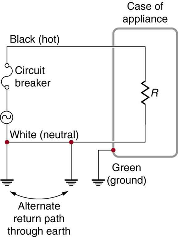
Figure 2.3.1 shows the schematic for a simple AC circuit with no safety features. This is not how power is distributed in practice. Modern household and industrial wiring requires the three-wire system, shown schematically in Figure 2.3.2, which has several safety features. First is the familiar circuit breaker (or fuse) to prevent thermal overload. Second, there is a protective case around the appliance, such as a toaster or refrigerator. The case’s safety feature is that it prevents a person from touching exposed wires and coming into electrical contact with the circuit, helping prevent shocks.
The following diagram demonstrates a safe circuit design (if you do not know all of the symbols, we will learn them in the next module). As you can see below, a safe circuit design has a source of energy (such as a battery) which is connected to a ground point. There is going to be a ‘load’ on this circuit (the symbol is shown as resistance as the load will offer some resistance to the circuit) and in many cases the load will be a piece of biomedical equipment. You can see a slightly more complicated schematic on the right where an electrical appliance with a metal case is plugged into the circuit. You will notice that there is no voltage between the case and the ground.
What happens when there is voltage between the case and the ground? Accidental contact can provide a pathway for electricity to travel which will result in you getting shocked.
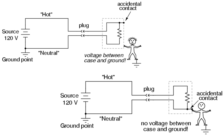
You may have noticed the above diagrams are demonstrating a piece of biomedical equipment that only uses two prongs: one ‘hot’ and one ‘neutral’ prong. What does a circuit using a three-prong piece of biomedical equipment look like? As you can see, having a ground point ensures there is no voltage between the case and the ground
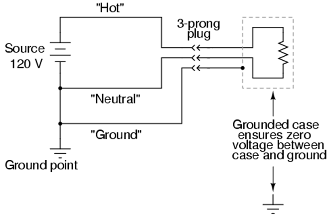
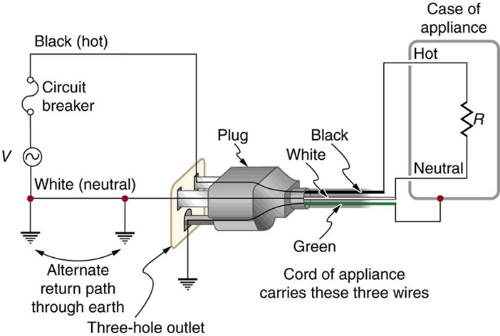
There are three connections to earth or ground (hereafter referred to as “earth/ground”) shown in Figure 2.3.2. Recall that an earth/ground connection is a low-resistance path directly to the earth. The two earth/ground connections on the neutral wire force it to be at zero volts relative to the earth, giving the wire its name. This wire is therefore safe to touch even if its insulation, usually white, is missing. The neutral wire is the return path for the current to follow to complete the circuit. Furthermore, the two earth/ground connections supply an alternative path through the earth, a good conductor, to complete the circuit. The earth/ground connection closest to the power source could be at the generating plant, while the other is at the user’s location. The third earth/ground is to the case of the appliance, through the green earth/ground wire, forcing the case, too, to be at zero volts. The live or hot wire (hereafter referred to as “live/hot”) supplies voltage and current to operate the appliance. Figure 2.3.5 shows a more pictorial version of how the three-wire system is connected through a three-prong plug to an appliance.
Lets take a closer look at the three-prong set-up. Last week, we learned about the representation of different coloured wires and you will have to apply that knowledge below. Here we have a piece of biomedical equipment (on the left called ‘Case of appliance’) that has three prongs (black wire = hot wire, white wire = neutral wire, green wire = ground). The case of the equipment is attached to the ground wire which provides a pathway to the earth. As you can also see, the black wires connect between the power source and the equipment and the same holds true for the white wires. There is a circuit breaker in the power source, that denotes this is likely a GFCI plug.
Attributions
Unless otherwise noted, the content of this chapter is adapted from “23.8. Electrical Safety: Systems and Devices” College Physics, 1st edition by Paul Peter Uron, Roger Hinrichs, Openstax and is under a Creative Commons Attribution 4.0 International License. Access for free at https://openstax.org/books/college-physics/
- Figure 2.3.3 “Chapter 3: Safe Circuit Design” from Lessons in Electric Circuits by Tony Kuphaldt, All About Circuits, and is under a Design Science License
- Figure 2.3.4 “Chapter 3: Safe Circuit Design” from Lessons in Electric Circuits by Tony Kuphaldt, All About Circuits, and is under a Design Science License
