2.4 – Safe Circuit Design
Leakage current
Many electrical devices have a ground. Watch the following video on what a ground is:
![]() To learn how to access the transcript for this video, see “YouTube transcript instructions (opens a new window)”
To learn how to access the transcript for this video, see “YouTube transcript instructions (opens a new window)”
Why should you ground biomedical equipment?
As described in Section 2.2, a large current may create undesirable situations such as: Heart fibrillation, tissue injury, organ failure or even death. It will also avoid shock hazards such as macro and micro shock
In the previous section, we discussed the low frequency effects of electrical current. Now, lets move on to the high frequency effects.
The threshold current triggering physiological effects increases with increasing frequency. The “Let-go” current increases from 10 mA to 90 mA when frequency is increased from 60 Hz to 10 kHz. With very high frequency current (e.g. 500 kHz) such as that used in electrosurgical procedures, it will not cause muscle or nerve stimulation and will not cause ventricular fibrillation. However, skin burn and tissue damage can still occur at high current. With even higher frequencies (100kHz upwards), the capacitance is more important and the skin impedance reduction causes heat. It is possible to pass large currents at high frequencies because the neuromuscular effect are much reduced at HF.
Leakage current
Leakage current is not a result of a fault. It flows between any energized parts of an electrical circuit and its grounded parts. Generally has two components:
- Capacitive: Capacitive leakage current exists because any two conductors separated in space have a certain amount of capacitance between the conductors: stray capacitance
- Resistive: The resistive component of leakage current is primarily due to imperfect insulation between conductors: relatively small magnitude and is often ignored.
Example: General Hospital High-Voltage Circuit
The following is a general circuit for electricity in a hospital. As you can see there is a large amount of voltage coming in from the city. Transformers will step down this electricity to the different voltages needed at different outlets. You will also notice there is a ground.
Why do we need a ground for electricity in a hospital? As you can see in the ‘Ungrounded case’ below, a fault may cause electricity to travel along the chassis of a piece of biomedical equipment causing shock to the user. The ‘Grounded case’ provides an alternative route for the electricity; thus, protecting the user.
In a hospital, all the receptacle grounds and conductive surfaces in the vicinity of the patient are connected to the patient-equipment grounding point. Each patient-equipment grounding point is connected to the reference grounding point that makes a single connection to the building ground. See schematic below for an example of how this operates.
Protection Circuits
1. Ground fault circuit interrupter (GFCI)
A Ground Fault Current Interrupter (GFCI or GFI) is a safety device found in areas of the hospital that are potentially wet. Its wiring works based on electromagnetic induction. GFCIs compare the currents in the live/hot and neutral wires. When live/hot and neutral currents are not equal, it is almost always because current in the neutral is less than in the live/hot wire. Then some of the current, again called a leakage current, is returning to the voltage source by a path other than through the neutral wire. It is assumed that this path presents a hazard, such as shown in Figure 2.3.7. GFCIs are usually set to interrupt the circuit if the leakage current is greater than 5 mA, the accepted maximum harmless shock. Even if the leakage current goes safely to earth/ground through an intact earth/ground wire, the GFCI will trip, forcing repair of the leakage.
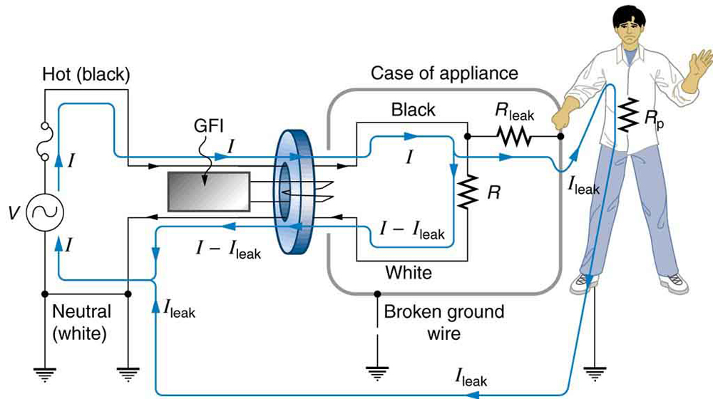
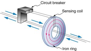
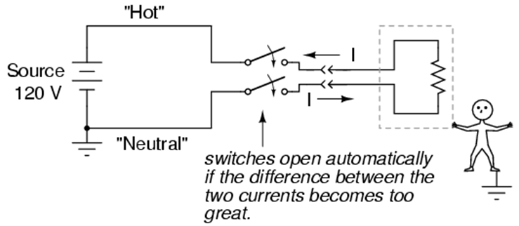
Figure 2.4.2 and 2.4.3 shows how a GFCI works. If the currents in the live/hot and neutral wires are equal, then they induce equal and opposite emfs in the coil. If not, then the circuit breaker will trip.
2. Isolation Transformer
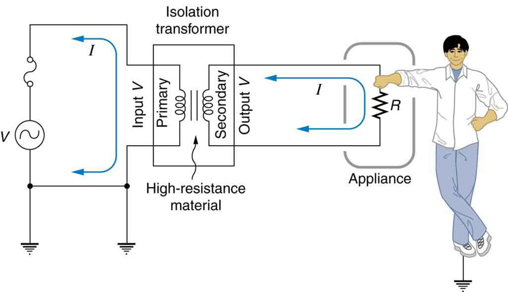
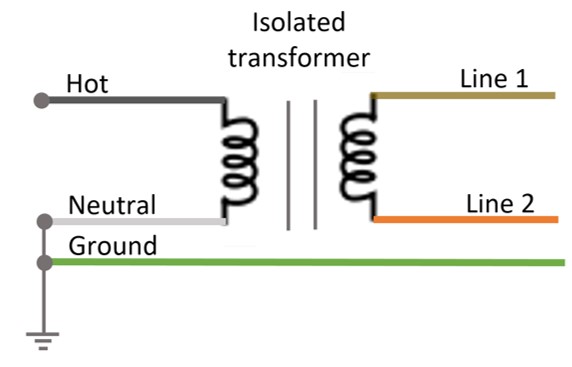
Another induction-based safety device is the isolation transformer, shown in Figure 2.4.4. In order to reduce microshock hazard, patient applied parts in contact with the heart or major blood vessels (C-type applied parts) are electrically isolated from the power ground. This is achieved by using an isolation barrier with electrical impedance of over 10 MΩ such that the leakage current is lower than 10 μA. The power is supplied to the components before the signal isolation barrier are isolated. There are two different ground references in an isolated patient applied part medical device: ground reference for the non-isolated part of the circuit are connected to the power ground and a ground reference for the isolated components are connected to the ground reference of the isolated power supply. These two grounding references are not connected together and are differentiated by two different grounding symbols. In all isolated power systems, there is no neutral wire as both lines connected to the secondary of the transformer are not tied to ground – they are floating with respect to ground (has no conduction path to ground). The voltage between the lines is 120 V. As shown in Fig. 2.4.5, the color coding for the line 1, line 2, and ground conductor of an isolated power system are:
- Brown – Line 1
- Orange – Line 2
- Green – Ground
Both line conductors are protected by circuit breakers that are mechanically linked together. A short circuit to ground will not produce any significant current as none of the line conductors are connected to ground (no return path exists for the fault current). As a result, fire and explosion hazards due to ground faults are eliminated. Line isolation transformers were required by building codes in operating rooms to prevent explosion hazard when flammable anesthetic agents were used.
Most isolation transformers have equal input and output voltages. Their function is to put a large resistance between the original voltage source and the device being operated. This prevents a complete circuit between them, even in the circumstance shown. There is a complete circuit through the medical device. But there is not a complete circuit for current to flow through the person in the figure, who is touching only one of the transformer’s output wires, and neither output wire is grounded. The appliance is isolated from the original voltage source by the high resistance of the material between the transformer coils, hence the name isolation transformer. For current to flow through the person, it must pass through the high-resistance material between the coils, through the wire, the person, and back through the earth—a path with such a large resistance that the current is negligible.
3. Line Isolation Monitor (LIM) monitor
A LIM is usually set to sound an alarm when the ground current exceeds 5 mA. A LIM can detect a ground fault in an isolated power system as well as deterioration of the insulation between line conductors and ground. It cannot detect a broken ground conductor nor can it eliminate microshock hazards. These are found in critical care areas of the hospital as they alert the user there is a problem without shutting off power the the equipment.
Hazards
Below are some common hazards that you need to be aware of when working with biomedical equipment:
- Ground referenced Mains supply
- Faults in mains plugs and leads
- Leakage and auxiliary currents
- Loss of ground in class I equipment
- Mains distribution boards
- Wet skin
- Inability to release source of current
- Ignorance of electrical hazards
Attributions
Unless otherwise noted, the content of this chapter is adapted from “23.8. Electrical Safety: Systems and Devices” College Physics, 1st edition by Paul Peter Uron, Roger Hinrichs, Openstax and is under a Creative Commons Attribution 4.0 International License. Access for free at https://openstax.org/books/college-physics/
- Figure 2.4.3 “Chapter 3: Safe Circuit Design” from Lessons in Electric Circuits by Tony Kuphaldt, All About Circuits, and is under a Design Science License
- Figure 2.4.5 Isolation transformer wiring colours by Soheil Ghoreyshi is licensed under CC BY 4.0
References
- Galco TV. Electrical Grounding and Why it’s Important – A Galco TV Tech Tip [Video] (2017). YouTube. https://www.youtube.com/watch?v=J4FqvMXgUX0
