3.3 – Basic Troubleshooting

Troubleshooting involves determining why a correctly designed piece of equipment is not functioning as it was intended. It provides an explanation for the faulty behavior being that the particular piece of equipment under consideration is at variance in some way with its design. To troubleshoot, a sequence of measurements must be made to localize this point of variance, or fault.
The problem for the trouble-shooters is to determine what a particular measurement tells him/her/them and what measurement to make next.
The way to obtain new information about the circuit is to make a measurement. In troubleshooting, new information is provided by coincidences (do not confuse this term with trying to coincidentally or accidentally find the problem). In the most general sense a coincidence occurs when a value at one particular point in the circuit can be deduced in a number of different ways. Such a coincidence provides information about the assumptions made in the deductions. A coincidence can occur In different ways:
- It can be the difference between an expected value and a measured value (e.g. expected output voltage of the power supply and the actual measured value);
- It can be the difference between a value predicted by Ohm’s law and a measured value;
- It can be the difference between an expected value and the value predicted by the circuit designer.
A troubleshooting investigation into a particular circuit proceeds in two phases. The first involves discovering more values such as currents and voltages occurring at various points in the circuit, and the second involves finding coincidences. The usefulness of coincidences is based on the fact that nothing can be discovered about the correctness of the circuit with a measurement unless something is known about the value at that point of the circuit in the first place. If nothing Is known about that point, a measurement will say nothing about the correctness of the components.
One actual measurement implies many other values in the circuit. The first phase of the investigation involves discovering many such values in the circuit, and the second involves making measurements at those points for which we know the implied values so that we can see whether the circuit is acting as it should, or if something is wrong.
Digital Multimeter (DMM)
A digital multimeter is going to be a troubleshooters best friend as it is the most important tool for determining electrical failures. As I discussed above, troubleshooting involves discovering values such as currents and voltages at various points in a circuit. How do you identify these values? Your DMM. It can allow you to determine AC and DC voltage and current, resistance and on some meters capacitance, transistor tests, diode tests and current and voltage frequency.
A simple/cheap multimeter may be appropriate for work you conduct around your house but I would recommend using a more expensive DMM on the job site as it will provide a higher degree of accuracy. In addition, inexpensive meters will not have as many features or the high internal resistance as seen in expensive meters. The features may not always be necessary but the internal resistance (impedance) is very important
Figure 3.3.2 shows a typical DMM, although different makes and models may have a different number of digits in the display unit and the input/output jacks may be in slightly different positions. Since a DMM is an important tool, you will want to learn how to use one correctly.
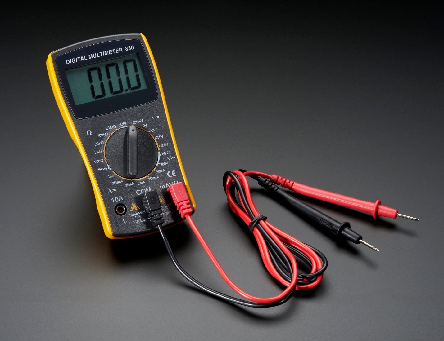
The upper portion of the DMM houses the display unit. The middle portion of the DMM houses the function switch, and the bottom portion contains the jacks for test leads. The function switch normally has positions that will allow a technician to measure:
- AC/DC Volts (V)
- AC/DC Amps (A)
- Resistance Ohms (Ω)
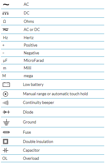
In addition, some DMMs have function switch positions that will allow a technician to measure and to test diodes and capacitors. Some DMMs require manual setting of ranges; others have an auto ranging feature. All DMMs may be used to measure voltage, current, and resistance. More advanced DMMs may measure frequency, relative power differences, or other important circuit parameters. Each measurement function has similarities and differences that you need to learn about. Many meters will use symbols on the display, switch, and connections. Figure 3.3.3 lists some of the common symbols you may see.
Rules when using an DMM
- If possible, take measurements with device powered off
- Some electronics with have test points (device will usually need to be powered on)
- Remove jewelry or objects that can conduct electricity
- DO NOT let conductive probes touch each other when they are both in contact with different test points/voltages in a circuit
- If you do this in a non-powered circuit, then your measurements will be wrong and may lead you down a faulty troubleshooting path
- If this occurs in a powered circuit, it will immediately short circuit
- Consider each meter unique (pay attention to meter specifications and signal limits)
- Do not hold meter probes by their tips or use probes that have bad insulation
- Do not exceed limits on the meter
- Current must be measured in series (ammeter, see right)
- Voltage is measured in parallel with the circuit or component to be measured (Voltmeter, see right)
- Do not attempt to measure resistance on a powered circuit – At least: blown fuse, Worst case: death
Tips when using a DMM
- Make sure your meter is working correctly
- An analog meter will show 0 when dead
- A digital meter will not show an LCD reading when dead, but will show 0 if the input lead fuse is blown
- DMMs have a very high internal resistance (several hundred megaohms); thus, they will not alter the current or voltage while providing very precise measurements.
- If you have to make measurements on two points a long distance away, do not use the chassis or frame as the return. Get longer leads.
- An inexpensive meter may be all you need in certain circumstances. When you drop it, use it incorrectly, leave it in a hot car etc. you will not feel so bad
- The most common mistake using a DMM: attempting a measurement with improper selection of meter ‘positioning’ i.e. meter is set to measure AC current when you are attempting to measure DC current
Troubleshooting Using a DMM
There are really only two rules for troubleshooting using a voltmeter. They are simple and always true:
- If you measure a voltage across a switch, the switch is open.
- If you measure a correct voltage across a load and the load doesn’t work, the load has failed.
With digital meters, voltage readings that are considered as zero will often indicate very small voltage readings. For example, when reading across a closed switch, a very small reading could indicate a very slight resistance across the switch contacts or even a meter inaccuracy.
Notice that the first rule does not say that if you read zero volts across a switch, the switch is closed. There are many situations in which you might read zero volts across an open switch.
The second rule indicates that the load has failed. This only means that the problem is with the load and you don’t have to look anywhere else for the problem. The actual remedy still has to be determined. This may require a replacement of the load, but there may be other possibilities. For example, there may be an overload that needs resetting.
Always look for the easy fix first. Check components that are easily accessible first that might explain the symptom that you have observed. For example, one of the first checks is to verify the power supply.
Voltage Tests
You can troubleshoot a problem using either a volt or ohms test. It is most practical to choose voltage testing. With a resistance test, you have to first disconnect the component being tested from the circuit, and while you are removing the wiring you could jostle things and possibly change the circuit, which may temporarily remedy the problem. In other words, you may not really find the problem.
When you use your voltmeter to troubleshoot, you will find either a switch that is open or a load that has failed. You can do this without moving any wires and without changing the circuit in any way. You may then remove the device and double check it with your ohmmeter.
VOLTAGE DROPS IN SERIES CIRCUITS
In series circuits, the total voltage is the sum of the individual voltage drops in the circuit, and the equation E = IR is used to calculate the voltage drop across each resistor. Since the current is the same through each resistor, the voltage drop across each resistor is directly proportional to the value of resistance. In other words, the greater the value of a resistor in a series circuit, the higher the voltage drop. Consider the simple series circuit in Figure 3.3.5
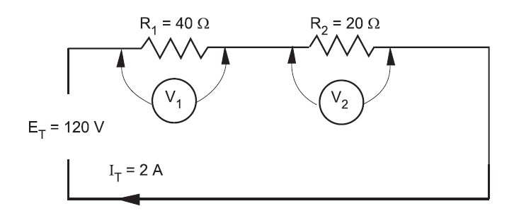
From the values given above, you can easily calculate the voltage drop across each resistor by:
E1 = I1 × R1 = 2 A × 40 Ω = 80 V
E2 = I2 × R2 = 2 A × 20 Ω = 40 V
The voltage drop of 80 V across the 40 Ω resistor is twice the voltage drop across the 20 Ω resistor.
Refer to Figure 3.3.6, If an open is introduced between resistors R1 and R2 (for example, by disconnecting a lead), current flow through the circuit is, of course, interrupted. If there is no current flow, the voltage drop across each of the resistive elements is zero (since E = I × R).
However, the potential difference of the source still exists across the open. If a voltmeter is connected across the open, the reading is the same as if it were connected directly across the terminals of the supply source.
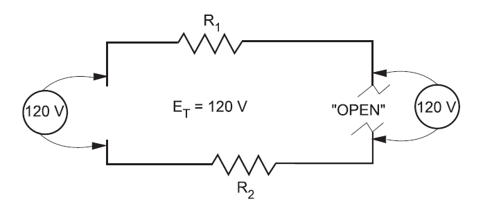
In a series lighting circuit, you could easily determine which lamp was burnt open simply by measuring the voltage across the lamp-holder terminals, in succession, until you have measured the total source voltage.
Testing Resistance (Ohms) with a Digital Multimeter
This test, using a digital multimeter, determines whether:
- an electrical circuit is complete or broken
- the resistance of a component matches the manufacturer’s specification
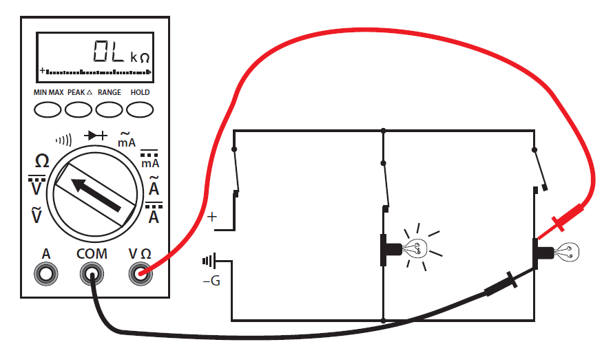
Follow these steps to complete the resistance test procedure:
- Make sure all power is off on the circuit you are testing.
- Make sure that the component that you are testing is isolated from the complete circuit. Either remove the component from the circuit or isolate it with an open switch.
- Set the selector dial to Ω.
- Connect the test lead and probes to the component terminals as shown (Figure 4).
- Observe the readout window to obtain the Ω reading.
- Compare the results to the manufacturer’s Ω specifications. If the readings match the component, then resistance is not a problem. If the component is a load, there should be resistance that matches the manufacturer’s specs.
- If the reading is infinite (I) or overloaded (OL), then the component is open.
- If the reading is zero, then the component is closed (if it is a load then this is an internal short).
- If this is the last test you are doing, turn the meter to “off” and store it in a safe place.
Troubleshooting Series Components
Sometimes you will be required to troubleshoot a piece of equipment that has stopped working. The first thing you would check for is power. Is the breaker off? Is the switch off? Is there a general power outage?
Once you have determined that power is still available you can begin using the multimeter to locate the problem. Starting with the first component or the one easiest to check, work your way through the circuit until you reach the component that shows no voltage reading. This is known as hopscotch voltage readings. Figure 3 illustrates this process. The dashed line indicates where the probe has already been placed and removed.
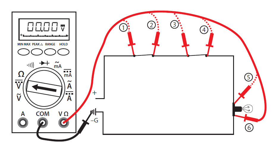
Follow these steps to complete the voltage test procedures with an autorange meter:
- Set the selector dial to the type of current to be tested: AC or DC.
- Once you have determined that the load (shown as a lightbulb) is not working, check for voltage across the light first to verify rule #2 (i.e., if you measure a correct voltage across a load and the load doesn’t work, the load has failed.).
- If you have voltage across the light, then the light has failed. If there are zero volts across the light, then one of the switches or wiring connections in the circuit has failed. If you have a zero reading across the light, continue with the next steps.
- Place the black probe at a grounded component.
- Place the red probe and check for a voltage reading at each test point in order starting at test point 1, verifying power supply.
- Continue working your way through the circuit until you get a zero reading, which would indicate a break in the circuit just before that point.
- Reading at 2 = switch #1 closed, zero at 2 = switch #1 open
- Reading at 3 = wiring to switch #2 good, zero at 3 = wiring to switch #2 open
- Reading at 4 = switch #2 closed, zero at 4 = switch #2 open
- Reading at 5 = wiring to light good, zero at 5 = wiring to light open
- Reading at 6 = load is energized, zero at 6 = the load is open (although you have already checked the load in your first test). If you get to this stage and the load is energized, the only component left that must be faulty is the final wiring from the load to ground.
- Once the open in the circuit has been identified, you can de-energize the circuit, remove the component, and double check the component with your ohmmeter.
- If this is the last test you are doing, turn the meter to “off” and store in a safe place.
Electrostatic discharge (ESD)
ESD is the sudden discharge of static electricity that we build up when we walk around. Although a slight annoyance for us, it can be devastating on electrical devices. You may not even notice a charge than can destroy electronics. Always check ESD labels (see photo on right) on biomedical equipment but even if there is none, assume that it is ESD sensitive.
Relative humidity (RH) of an area has a large effect on the build-up of static electricity. Areas of low RH will have a larger ESD danger. High RH will have problems with moisture and mold but fewer ESD problems. Walking across a carpet in low RH can = 35 000 V while in low RH 1 500 V. A worker walking around a work bench in low RH can generate 6 000 V. Remember, even 100 V can destroy some ESD sensitive equipment
3 categories of ESD to biomedical device
- Catastrophic: device is useless after this event
- Latent: appears to be no damage but life of the component is severely shortened
- Upset: temporary loss of biomedical equipment functioning but will resume operation with no degradation of performance
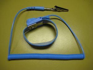
In order to prevent ESD, a technologist can wear an anti-static wrist strap (also known as ESD wrist strap or ground bracelet, see photo below). This device prevents the build-up of static electricity on a technologist while they are working on sensitive biomedical equipment by safely grounding them.
Attributions
Portions of this chapter, including figures 3.3.3 to 3.3.8, have been adapted from Multimeters 101: Basic Operation, Care and Maintenance and Advanced Troubleshooting for the Skilled Trades by B. Phifer is licensed under CC BY 4.0
- Figure 3.3.1 – “Computer Circuit Board,” by Harland Quarrington, courtesy of Defence Imagery ©Crown Copyright. Licensed under an Open Government License.
- Figure 3.3.2 – Digital Multimeter – VIC830 by Adafruits Industries courtesy of Flickr and under a CC BY NC SA 2.0
- Figure 3.3.9 – Electrostatic Discharge Symbol (ESD) by OpenClipart courtesy of FreeSVG. Public Domain.
- Figure 3.3.10 – Electrostatic Wristband by KMS courtesy of Wikimedia and is under a CC BY 3.0 license
