3.2 – Medical Device Analyzers
Medical Device Analyzers
Technological developments have led to significant improvements in the performance of more advanced models of biomedical equipment. This has resulted in more complicated circuitry among numerous CPU boards and sensors. There are now more possible weaknesses which can lead to breakdowns. Therefore, increased special maintenance of medical equipment is necessary.
Medical equipment analyzers
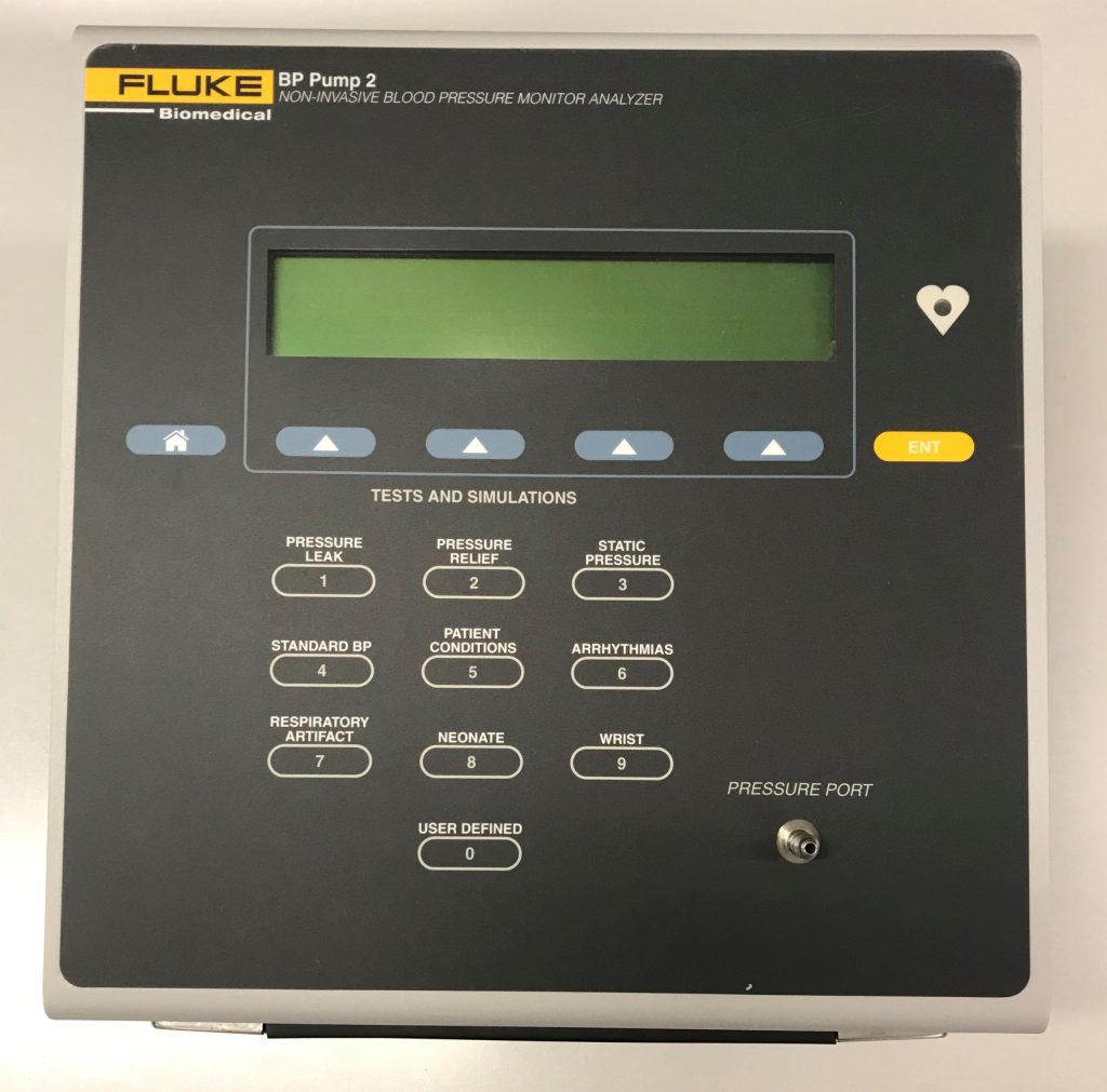
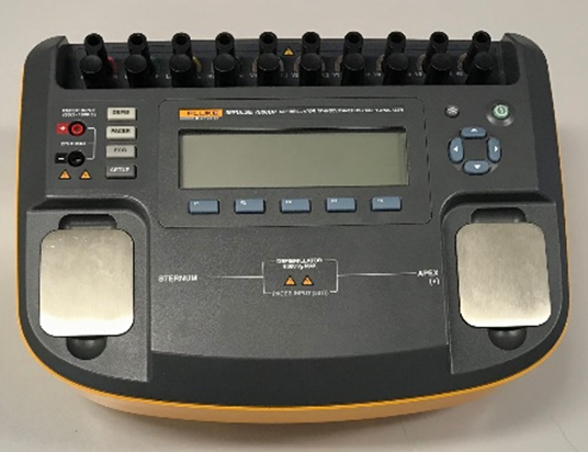
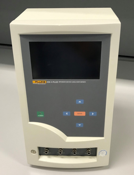
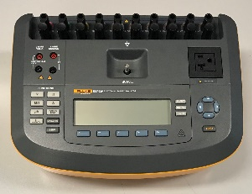
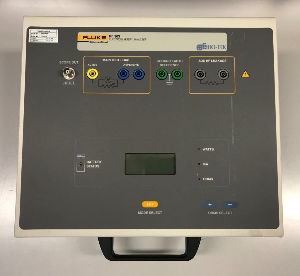
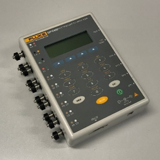
The inspection of medical equipment is evaluated using various analyzers. Replacing faulty parts in house at Biomedical department contributed to more prompt responses and less repair costs. As you can see in the examples below, tester or analyzers come in many different shapes and sizes and are usually equipment specific.
Who uses medical device analyzers? Clinical engineers or Biomedical Technologists maintain medical equipment, specifically by those who trained to use a specialized analyzer. Clinical engineering has decreased medical equipment failure which exposes patients to fewer potentially harmful risks.
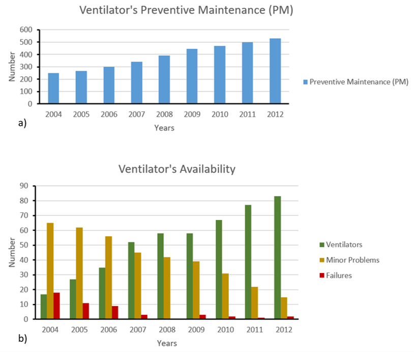
What would be the main benefit of having Clinical engineers or Biomedical Technologists at Hospitals? Having Clinical engineers or Biomedical Technologists helping health care facilities to provide higher quality care to patients and lower the cost of care for hospitals. As an example having more scheduled preventive maintenance on medical devices like as ventilators at the beginning in short term it might shows an increase of cost for hospitals but in long term it provides more available ventilators with minimum risk of failure to the patient. The following graph could be an example of practical study at a health care center or hospital. As you can see, the number of ventilators that are available go up while the number of minor problems and failures go down with use of proper analyzers and preventive maintenance plan.
Current Developments to Streamline Patient Care
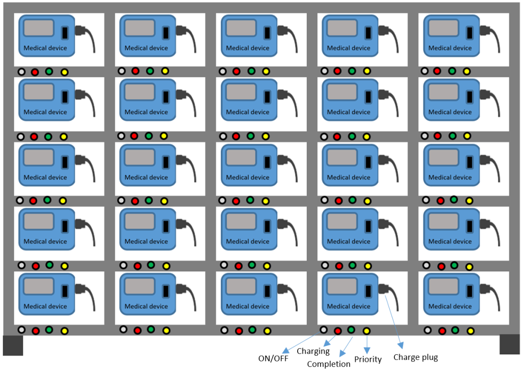
In addition to modern preventive maintenance strategies, continuous live support for small chargeable medical devices would be extremely beneficial. For example, the following schematic represents an efficient battery charging management system for battery equipped medical equipment. This system has an indicator to show the current charging level of the medical devices. Also, medical devices with priority charging can be identified by the LED indicator on the charging rack. Similar charging stations can be found in a hospital setting.
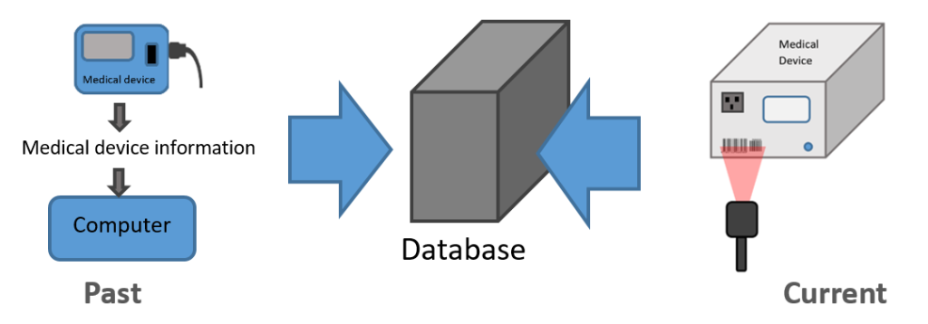
The data entry tool scans the barcode of medical equipment and provides a complete history of medical equipment in the Biomedical Department as a part of the management plan. Any medical devices coming into or going out of the biomedical department must be scanned by the barcode reader.
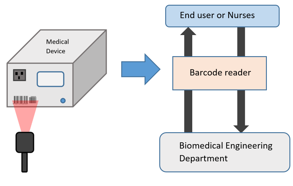
Traditionally, a user manually inputs device information (model, serial number, etc.) into an original data management system. It takes time and effort. The barcode reader system eliminates the need for manual data entry. It will remove possible human mistakes, confusion, and inappropriate usage of medical devices (e.g., device failure, wrong patient, different material, different medicine, or user ID).
Maintenance and Troubleshooting
Preventative Maintenance (PM)
PM (not to be confused with project management) is conducted to make sure that the medical equipment is safe and in proper working order. Equipment should be inspected to ensure that it is calibrated accurately. PM can protect the patient by reducing the likelihood of mistakes when the equipment gives inaccurate data. PM procedures are recommended by the manufacturers of equipment and are usually given in the equipment service manual. The frequency of PM depends on how vital the instrumentation is and on the observed failures (blood circulation or breathing devices more than other).
Wearing parts of equipment must be changed periodically: X-ray tubes, chemical electrodes or air filters. Inoperative equipment should go through the troubleshooting process and repaired.
Principles of troubleshooting
Troubleshooting is: A systematic approach that should be taken to locate the cause of a fault in an electronic circuit or system. Example: If your keyboard will not type, check to ensure that the cable is securely fastened to the keyboard port.
It is: A way of determining which part of a system is responsible for a problem. Example: sensing electrode, reference electrode, instrument, solution, measuring technique and operator. Unexpected solution chemistry, incorrectly prepared standardizing solutions, improper plotting of data, unsuitable reference electrodes, operator error and poor choice of method account for many more problems than do instrument or electrode failure.
It is: a logical way of testing hardware or software in order to determine how to fix a problem
Troubleshooting is done by one of the following methods:
- Case-study approach is used if a piece of equipment were known to have a chronic, or repetitive, problem. Check to see if it had reoccurred before looking for other problems.
- Logical analysis of given evidence. Data relating to the problem is gathered and used to isolate the case analytically. Because circuit theory is basic to design of medical equipment, it could be used to deduce every problem with the hardware.
A systematic approach to troubleshooting uses both methods. The repair procedure will involve systematic disassembling and reassembling of the equipment.
- To disassemble the equipment, number each part as you remove it.
- Then to reassemble, replace the parts in the reverse order, in order to be sure you are putting all the parts back together correctly.
The following is a flow diagram outlining logical steps to troubleshooting. Follow the steps indicated until the problem is identified:
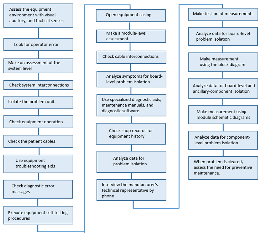
The following provide some detail about a few of the above steps from Figure 3.2.11:
Step 1: Before doing anything, do a visual inspection on medical devices for any physical damages or any abnormal signs.
Step 2-5: After visual inspection, answer this question. Is there a medical device operating error? Then make an assessment in system level by checking the system interconnection and isolate the problem unit.
Step 6, 7: Check the medical device operation and check the patents cable (applied parts) .
Step 8-10: Use the testers or analyzers as troubleshooting aids. Check the diagnostic error massages on display and execute the available self-testing procedures through the medical device.
Step 11-13: Open the equipment case and perform the module level assessment. You need to check the interconnection cables too.
Step 14, 15: Analyze the symptoms in module or board level with using recommended manufacturer instruction with software or service manual.
Step 16-18: Check the medical device history at biomedical department. Analyze the data and consult manufacturer technical representative.
Step 19-21 Do the data analysis based on the gathered or measured data from designated test points. The data analyze provides a broad perspective on the kinds of problems that the equipment may be susceptible to.
Step 22-24: data can be used to isolate the problem either to a particular board or to an ancillary component
Step 22: When the problem is clearly diagnosed assess a need to future preventive maintenance plan.
First Line Maintenance/Troubleshooting tool kit
Table 3.2.1
Example of a basic tool kit for first line maintenance of biomedical equipment.
| Tool | Specifications | Number Required |
|---|---|---|
| Allen Keys | 2-10 mm | 1 set |
| Brush (paint, flat) | 25 mm | 3 |
| Brush (paint, round) | 2 cm diameter | 3 |
| Funnel (plastic) | 100 mm diameter | 2 |
| Grease Gun | / | 1 |
| Hammer (claw) | 450 g | 1 |
| Hammer (plastic/leather) | 280 g | 1 |
| Knife (retractable) | / | 1 |
| Knife Blades | / | 1 set |
| Oil Can | / | 1 |
| Pliers (slip, joint) | 24 mm – 2 positions | 1 |
| Pliers (water pump) | 25 mm – 5 positions | 1 |
| Pliers (combination) | 125 mm insulated | 1 |
| Pliers (longnose) | 125 mm insulated | 1 |
| Plier Cutters | 125 mm insulated | 1 |
| Screwdrivers (flat) | 3.2 – 8 mm insulated | 1 set |
| Screwdrivers (star) | No.0 – No.3 insulated | 1 set |
| Spanners (flat) | 9 mm – 22 mm | 1 set |
| Spanners (flat) | 9 mm – 26 mm | 1 set |
| Tape Measure (retractable) | 3 meters | 1 |
| Tool Box (lockable) | Steel | 1 |
Circuit‐Board Troubleshooting
When a circuit board has been found to be faulty, component-level troubleshooting should be done. This involves:
- Detailed signal tracing
- Voltage and resistance measurements
- Use of the equipment schematic showing interconnection between the individual components.
If a particular circuit board should be replaced by another one, the following consideration should be taken:
- A visual inspection should be performed to look for any evidence of short circuits or overheating.
- Checking the power supply over-voltage, which could be damage the new board.
- Using of antistatic spray to prevent damage due to static charge buildup.
- Because the circuit boards are expensive, all precautions should be taken not to damage them during troubleshooting procedures.
Attributions
- Figure 3.2.1-Non-Invasive Blood Pressure Monitor Analyzer – BP Pump 2 by Soheil Ghoreyshi is licensed under CC BY 4.0
- Figure 3.2.2-Defibrillator Analyzer by Soheil Ghoreyshi is licensed under CC BY 4.0
- Figure 3.2.3-Infusion Device Analyzer by Soheil Ghoreyshi is licensed under CC BY 4.0
- Figure 3.2.4-Electrical Safety Analyzer by Soheil Ghoreyshi is licensed under CC BY 4.0
- Figure 3.2.5-Electrosurgery Analyzer by Soheil Ghoreyshi is licensed under CC BY 4.0
- Figure 3.2.6-Patient monitor/simulator by Soheil Ghoreyshi is licensed under CC BY 4.0
- Figure 3.2.7-Ventilator – Preventive Maintenance and Availability by Soheil Ghoreyshi is licensed under CC BY 4.0
- Figure 3.2.8-Medical device charging station by Soheil Ghoreyshi is licensed under CC BY 4.0
- Figure 3.2.9-The data entry tool by Soheil Ghoreyshi is licensed under CC BY 4.0
- Figure 3.2.10 -Barcode reader system by Soheil Ghoreyshi is licensed under CC BY 4.0
- Figure 3.2.11- Troubleshooting steps diagram by Soheil Ghoreyshi is licensed under CC BY 4.0
