Case 2:
Medical device:
| Make: | Hewlett-Packard |
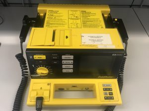 |
| Model: | CodeMaster XL+ | |
| Serial Number: | US00010863-Demo | |
| Applied part type: | CF | |
| Certified by: | UL & CSA |
Device problem:
Patient relay drive failure
Before taking any steps of repair or troubleshooting, it is recommended to Localizing the fault in the assembly level. Take the following steps while using the HP_CodeMaster XL+ service manual as your reference guide.
When the defibrillator is OFF follow the steps below.
Step 1: Move the “Energy Select” Knob from “Off (Standby)” to “Monitor On” while Pressing and holding the “HR Alarm” and “Syns” keys simultaneously. (figure 8)
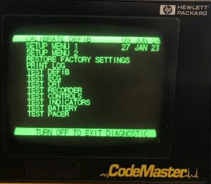
Step 2: From the following diagnostic menu select the PRINT LOG test.
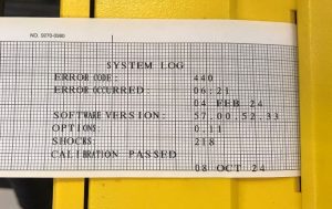
Step 3: Select the “PRINT LOG” from the menu. Print the error log to see if it contains an error code. (figure 9 and 10)
 |
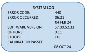 |
The system log shows the ERROR CODE “440”.
Step 4: Check the troubleshooting table of service manual for the “ERROR COD 440”, the manufacturer recommended possible solutions would be replacing either the patient relay (if the coil resistance outside the nominal range of 3 Ohms ± 1), high voltage board, or control board.
| Error Code | Error Description | Possible Solution |
| 040
400 440 |
A patient relay drive failure was detected. | 1- Check patient relay coil resistance, if outside nominal range, (3 Ohms ±1) replace patient relay.
2- Replace high voltage board 3- Replace control board |
Step 5: Turn off the defibrillator, remove the battery and disassemble the device for replacing the high voltage board.
| Figure (11-A) shows that the main top cover of the defibrillator’s enclosure is removed. The CRT module, High Voltage board, SPO2 board and High Voltage capacitor are visible. | 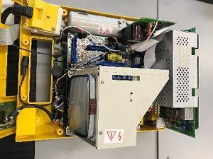
Figure 11-A |
| Figure (11-B) shows, the CRT module and SPO2 board are removed from the assembly. | 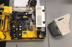
Figure 11-B |
| Figure (11-C) shows, the high voltage board removed from the assembly | 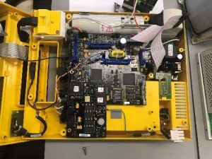
Figure 11-C |
| Figure (11-D) shows, the control board removed from the assembly. The patient relay is visible in the middle of this image. | 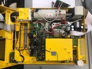
Figure 11-D |
| Figure (11-E) shows the patient relay | 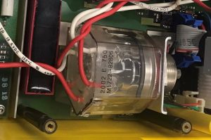
Figure 11-E |
Step 6: After disassembly and removing the faulty patient relay, replace it with the new Patient relay and assemble the defibrillator back into the original setup by using the service manual. Then run the diagnostic/performance test to validate the device.
.
Attributions
- All Figures are licensed under: Various Biomedical Equipment by Soheil Ghoreshyi is licensed under CC BY 4.0

