3.4 – System and Specific Troubleshooting Techniques
Troubleshooting
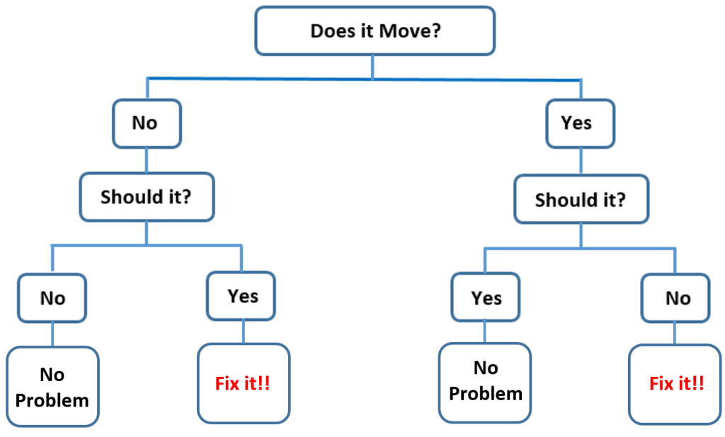
An understanding of wiring diagrams, schematics, flow charts and trees, visual recognition of the parts and their schematic symbols will help you in troubleshooting. Many repair manuals now include troubleshooting charts or trees. The following is a humerus example of a troubleshooting chart.
Troubleshooting is the act of identifying and correct problems in any kind of system. This is not a trait specific to biomedical technicians but is used in many professions such as plumbers and doctors. Troubleshooting occurs when there is multiple conflicting or seemingly unrelated observations. Cause and effect is difficult to determine even on simple systems
There are usually 4 parts to a troubleshooting tree
- Start point
- Series of questions
- Answering of ‘yes’ or ‘no’ to the questions
- End or conclusion
You will notice that there are many different troubleshooting trees and many different lists that outline the steps of troubleshoting. The usefulness of the trees/charts/lists depend on the questions being asked. If it is a new product, likely the tree is not as good as an established product as the manufacturer only asks questions that they think are probable/possible. Therefore, do not blindly accept the flowchart. Your experience should help guide you to the answer and the tree/chart/lists should only be one tool you use.
Here is one example of the 7 Troubleshooting Steps. As I said, if you look, you will notice lists that have 6 to 9 steps. Generally, the process is all the same, the different numbers for each list may go into more or less detail on what you have to accomplish.
- Observe the system operation and faults
- Clearly understand the problem
- Gather any additional information
- Isolate the problem
- Hypothesize a cause(s)
- Use the cause to determine the probably of its effect and other expected observations
- Perform experimental tests to determine the validity of your hypothesis
Once you find the cause, you are only half done. You still need to fix the problem.
Troubleshooting Questions
When you first approach a piece of equipment that needs repair, there are a few questions that you should be asking:
- Has the system worked before? Was it installed wrong?
- If the system did work before, has anything happened since then to cause the problem? Look at maintenance records
- Has the system proven itself to certain types of failures?
- How urgent is the need for repair? Is it just a minor fault?
- What are the safety concerns before you start troubleshooting?
Specific Troubleshooting Techniques
- Are there identical components? Are there parallel systems that are easy to remove and install? If there are, swap out identical components and see if the problem moves with the swapped component. This will provide a positive and negative indication of the problem. Or the problem still exists but has changed in some way (calibration issue).
- Remove parallel components: If a system has parallel or redundant components, you can start removing them one at a time to see if things get better.
- Divide the system into sections and test those sections (see the half-step method of troubleshooting below): If the system has multiple sections, measure the variables in each section until you find a stage where the variables do not look right
- Trap a signal: Test equipment have allowed for troubleshooting over longer periods of time. This is helpful when a problem is intermittent. Use a data logger or recorder to monitor signal over a long period of time
- Failures in Proven systems (successfully operating for some time; ranked from most to least likely)
-
- Operator error
- Bad wire and bad connections
- Power supply problems
- Active components (amplification devices)
- Passive components (semi-conductors, capacitors)
- Failures in Unproven systems (ranked from most to least likely)
-
- Wiring problems
- Power supply problems
- Defective components
- Improper configuration
- Design error
The order of most likely biomedical device failure to least likely biomedical device failure:
- Clinical failure (Use error)
- Mechanical failure
- Electromechanical failure
- Electronic failure
Clinical failure (Use error)
This category is the highest probable cause of medical equipment failure. Clinical failure includes
- Patient abuse
- Set-up error
- Displayed outputs do not agree with expected clinical results
- Machine is asked to perform a function it is incapable of
Mechanical failure
A mechanical failure is a physical breakage at some area of the device. Also it could be a disconnected harness connection in any circuits of the device.
Always look for obvious physical damage externally. Cords which can be run over and power cords connections are always good candidates for mechanical damage. Equipment with long hoses or cords attached to the patient may become entangled and cause the equipment to be pulled from shelves or cause tipping of caster-mounted devices.
Electromechanical failure
Most medical devices contain electromechanical components in the form of electric motors and relays. Relay and relay switching devices are the main source of electromechanical failure. Basic knowledge of electric motors, generators, and motor controls is essential for repair of this type of problems. Proper lubrication and cleaning prevent most of these failures. A good preventive maintenance (PM) program is highly cost effective and provides a means of inventory control.
Electronic failure
Although this is the most sophisticated form of repair, and involves the most training, due to the high level of development and technology transfer in electronics Electronic failure rarely occurs. When Electronic failures do occur it is usually a result of a failed cooling apparatus or to the dust build-up causing overheating of the electronic system. Board exchange is commonly used instead of board level component replacement. Knowledge of electronic troubleshooting can be tremendously cost effective.
WLO: Apply the “half-step” troubleshooting method
An efficient means of isolating electronic problems is a technique known as half-stepping. Mentally divide the problem area of the failed device into halves. Using the digital multimeter (DMM) and the one-hand rule test for voltage readings. Once a correct voltage reading is either found or lost, mentally divide the problem area into halves again. Continue applying the half-step method until you have isolated a small area of the electronic portion of the device.
Half-Step (or Half-Split) Method of Troubleshooting.
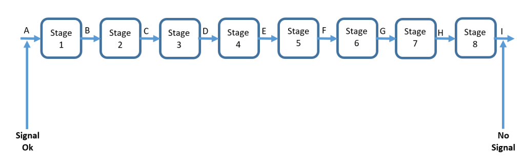
Half-stepping or splitting is a technique used in trouble shooting which reduces the average number of measurements needed to isolate the faulty stage or component. Consider the eight stage path shown in the figure above and the technique explained in the following paragraphs.
The first measurement using half-splitting would be made at point E (the middle of the faulty path). If the signal is okay at point E the path to the left of point E is good and the problem lies between points E and I. Thus one measurement has reduced the size of the faulty path by one-half (half-splitting). (2) The next measurement would be made at point G again splitting the faulty path in half. If the measurement at point G is bad (no signal) the next measurement would be made at point F. This method of splitting a faulty path in half is continued until the faulty stage is isolated.
WLO: Recognizing circuit loading and correcting the problem
Circuit comes from the word circle. A circuit is a collection of real components, power sources, and signal sources, all connected so current can flow in a complete circle.
- Closed circuit – A circuit is closed if the circle is complete, if all currents have a path back to where they came from.
- Open circuit – A circuit is open if the circle is not complete, if there is a gap or opening in the path.
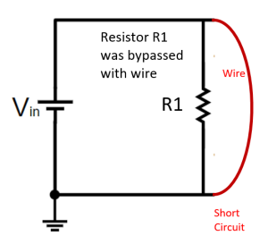
A Short circuit occurs when a path of low resistance is connected (usually by mistake) to a component. The resistor shown below is the intended path for current, and the curved wire going around it is the short. Current is diverted away from its intended path, sometimes with damaging results. The wire shorts out the resistor by providing a low-resistance path for current (probably not what the designer intended).
After applying the Half-Step Method the abnormal voltage readings obtained will be a result of open circuits or shorted circuits. An open circuit refers to an electronic problem caused by an incomplete circuit path, which prevent electron flow from the negative side of the circuit to the positive side of the circuit. As the name Open Circuits implies, there is an opening due to a failed component or physical damage to the circuit path. Open Circuits cause higher resistance in the system, since there is no current path through some or all of the components in the circuit.
Circuit loading is a common problem often associated with open circuits. This problem is a result of higher than normal resistance of the circuit. Circuit loading can be caused by loose board connectors or corrosion of the circuit path.
A shorted circuit is circuit that has a lower resistance due to a direct current path avoiding or bypassing normal resistance. A shorted circuit can be caused by internal circuit wires or leads breaking their normal connections and touching the circuit in a different location. A shorted circuit can also be created by solder that extends beyond the area intended to be soldered. Occasionally, a circuit path can be created by dust and grit build-up in a circuit if the dust contains conductive material such as metal flakes or room a room aerosol sprays.
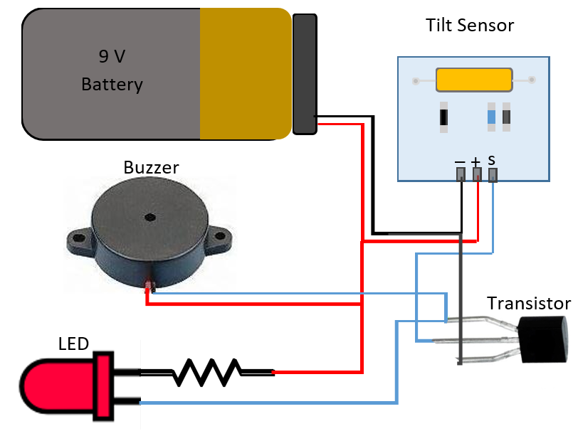
Troubleshooting exercise
Take 15 minutes to create your own troubleshooting tree (see above for the steps) for troubleshooting for this tilt sensor switch circuit. For example: Is there power to the unit? Y/N, if yes…then perform this next step. If no, then perform this step.
Attributions
- Figure 3.4.1-Troubleshooting chart by Soheil Ghoreyshi is licensed under CC BY 4.0
- Figure 3.4.2-Half-Step Method of Troubleshooting by Soheil Ghoreyshi is licensed under CC BY 4.0
- Figure 3.4.3-Short circuit by Soheil Ghoreyshi is licensed under CC BY 4.0
- Figure 3.4.4-Tilt sensor switch circuit by Soheil Ghoreyshi is licensed under CC BY 4.0
