5.2 – DC Brushed/Brushless, DC Stepper/Servo and AC motors
Regardless of AC or DC, motors will have a stator (stationary field) and rotator (rotating arm) and the interaction of magnetic flux and electric current to produce rotational speed and torque.
We will discuss three basic types of conventional electrical motors:
- DC motors: Brushed/Brushless
- DC motors: Stepper/Servo
- AC Motors
There are other types of motors available, such as linear motors. However, the motors mentioned above are commonly found in biomedical equipment and will be the focus of the following sections.
DC motors apply a constant torque even at low speeds; thus, are appropriate for equipment that requires a constant torque load such as in blower fans in Positive Airway Pressure (PAP) respirators (sleep apnea machines. Another benefit for this is that DC motors are quiet).
A stepper motor is another type of DC motor that divides its rotation into discrete number of equal steps. Stepper motors are ideal when you need equipment to move and hold at a particular location without the need for feedback from a sensor. A blood circulation scanners use a laser to determine adequate blood supply to living tissues. Stepper motors control the position of the laser.
Servo motors are basically a brushed DC motor with a feedback control mechanism. Equipment that would benefit from servo motors would be ones that require precise control of such as acceleration, velocity or linear/angular position. Centrifuges and medical robots are two biomedical applications that use servo motors.
AC motors operate on the same principles as DC motors but obviously use AC power. AC motors are used in equipment that require high efficiency and constant torque at rated speed. AC motors can be found in centrifuges and pumps.
DC Motors
DC motors are ubiquitous. They convert electrical/magnetic energy, produced by a wire carrying current in a magnetic field, to motion, and they appear in all sorts of appliances and applications, e.g., they are found in small fans, ceiling fans, air cleaners, solder fume extractors, hand-held rotary tools, cars, robots (where they rotate tires, or move robotic arms, etc.) and different biomedical equipment can also contain these motors. The most popular motors generally have shafts that are round, or ‘D’-shaped (i.e., flattened on one side), flattened on two sides, or geared (i.e., have gears directly cut into the shaft or mounted on the shaft). Although motors can run from DC, AC, and in the case of universal motors from both DC and AC, this section will only discuss DC motors in detail.
Electric current and magnetism go hand-in-hand as it is impossible to have one without the other (See Fig. 5.2.1). Magnetism produced by current flowing through a single wire is weak. If this wire is wound into a coil the magnetic field becomes stronger. If this coil is then wrapped around a ferrite core its magnetic field becomes even stronger.
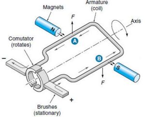
Figure 5.2.1 – Example of a brushed DC motor producing rotation through stationary magnets and an armature with current running through it creating an electromagnetic field
The theory of DC motors is not too difficult to understand, if we recall that for magnets opposite poles attract and similar poles repeal (See Fig. 5.2.2). A DC motor works by having the poles of a rotor through which current flows, thereby producing a magnetic field, subjected to another magnetic field which attracts the magnetic field of the rotor. It is interesting to learn that the opposite is also true. That is, as a motor rotates the interaction of the magnetic fields produces a voltage.
_50_degree_split_ring.gif)
Figure 5.2.2 – The armature windings are connected to a DC supply creating an electric current in the winding, the current carrying armature conductors experience a force due to the magnetic field causing them to rotate
Motors are devices that can impart motion. I.e., movement to a piece of biomedical equipment. Your main concerns with motors are speed and torque. Speed for motors is measured in rotations per minute (RPM) or radians/sec, e.g., 3,000 RPM or 450 rad/sec. (Note: these are but two examples of how motor speed might be represented. They are not meant to imply that 3,000 RPM is equal to 450 rad/sec; it is not). Fortunately, it is easy to covert from RPM to radians/sec or degrees/sec or the reverse. Speed is represented by the Greek letter omega, ω.
Torque is a “twisting/turning force”. Force is frequently measured in Newton (N), and when we multiply force by length we get torque, e.g., Newton-meters (N-m), Newton-centimeters (N-cm), or ounce-inches (oz-in). In a motor the torque is always tangent to a circle centered on the shaft, i.e., it is at a right angle to a diameter. The symbol designating torque is the lowercase Greek letter tau, τ, and less frequently the English capital letter T. Datasheets for DC motors usually provide speed in both RPM, and radians or degrees/sec. Torque is often presented in datasheets in several forms (e.g., as peak torque, stall torque (more on this later), and rated torque, etc. DC motor datasheets are usually quite comprehensive and present other motor parameters as well. It should be noted that motors can have the same power capability, but different speed and torque, as it is possible to exchange speed for torque
Watch
Video: The following video provides an excellent description of how DC motors work.
![]() To learn how to access the transcript for this video, see “YouTube transcript instructions (opens a new window)”
To learn how to access the transcript for this video, see “YouTube transcript instructions (opens a new window)”
Brushed DC Motors
There are four main parts to many continuous brushed DC motors:
- The rotor (the part that rotates) or armature (in engineering speak the armature is the component of an assembly that turns/pivots and that holds the main current carrying coils that produce a magnetic field) here the rotor and armature are the same, i.e., they are both the turning component in the center.
- The stator, as its name might suggest, is stationary, it provides the magnetic field that surrounds the rotor (it is often in two parts if the stator is made from a permanent magnet). If so, the stator magnets are known as field magnets. Field magnets are reliable, as the magnetic field remains at a constant level, although their fields may diminish with time. Permanent magnets are found in many brushed motors. If the stator is made from an electromagnet the coils used to produce this magnetic field are known as field windings or field coils.
- Commutator: Split ring that rotates with the rotor/armature
- Brushes/Contacts: Some decades ago DC motors used actual copper “brushes” that were held by springs and pressed against the commutator to shift current to the coils and keep the motors turning. Today DC motors have contacts that “brush” against the commutator, but true brushes are uncommon. Although actual brushes are not common, these devices are still referred to as brushed motors.
Advantages of brushed motors:
- Inexpensive
- Typically have operational lives that are longer than the devices they are part of
In a simple DC motor the armature connects to a DC power source to produce a magnetic field when current flows. However, when the armature moves orthogonal to the stator, i.e., at right angles to the stator’s magnetic field, there is almost no torque experienced. The momentum of the rotor usually carries it forward to continue spinning. To overcome this ‘defect’, a second armature coil at right angles to the first is added so that there is always one segment of the armature that is exposed to a higher magnetic torque, i.e., is receiving power while the rotor is in a stronger portion of the magnetic field of the stator. In most working DC motors (see attached photographs) there are several armature coils offset from each other. In general, the more windings a coil has the higher its resistance, and the greater its torque, but the slower its speed. These coils insure that the motor turns smoothly and always yields a high torque at all points in its rotation. The rotor is connected to a commutator, which is a component that allows the rotor coil to change polarity as required to rotate continuously. The commutator is usually just a simple cylinder with contacts that have insulating gaps between them to allow “brush” conductive elements to connect, in turn, to the DC power source (see attached photographs). That is, it provides a simple switch to change the DC input. The commutator is connected to the DC power source by contacts that “brush” against the contacts on the commutator.
Brushless Motors (BLDC)
Brushless motors do away with the problem of brush wear and sparking; therefore, they are often used for their long lives and safety in potentially hazardous environments. They can be found in robots and human controlled machinery (the Segway uses brushless motors), computer fans, cordless power tools and industrial and biomedical applications. Brushless motors can also be used in servos, where they provide greater stability. Brushless motors come in a variety of shapes, sizes, and voltages. However, brushless motors are more expensive than their bushed counterparts, so unless these motors are needed for their long lives or safety features (i.e., without the sparking that may occur with brushed motors), brushed motors may be the right choice.
Until the introduction of strong permanent magnets in the 1970s and 80s, brushless motors were restricted in the torque that they could deliver. However with the introduction of, e.g., neodymium (NeFeB) magnets (developed in 1982), perhaps the strongest and most often used of the rare-earth magnets, and transistors that could handle high voltages, the situation changed. Brushless DC motors are today able to deliver as much torque as brushed motors, and since the commutation function is done electronically, these motors do not need brushes. They have less parts, and a longer live expectancy (today exceeding 10K hours, or well over a year of continuous use), compared to the typical life expectancy of 2K to 5k hours (approximately 83 to 208 days of continuous use) for a brushed motor. That is, BLDC motors have approximately 2-5 times the life expectancy of a brushed motor.
BLDC motors are increasing in popularity as brushes/contacts can wear out, and may produce sparking. Brushed motors, as noted, are less expensive to manufacture and are commonly used in Maker projects. However, it is important to learn if their rotors rotate in bushings or ball bearings, as bushings have a shorter operational live. There will be more on brushless motors later in this tutorial.
DC brushless motors are becoming a more common and popular choice compared with DC brushed motors. Why is this?
- Troubleshooting/repair advantage: you can replace the rotor or the stator. There is only a rare chance you have to replace the whole motor
- More power
- Less noise
- Less maintenance
However, choosing a motor will depend what purpose you want the motor to achieve (we will discuss later)
Brushless and stepper motors are essentially the same. The primary difference is how they are used. While a stepper motor is expected to move to a particular angular position, a BLDC motor is usually run to provide a continuous rotary motion. Also a BLDC motor usually has fewer steps than a stepper. For example, some BLDCs have only four steps per revolution, while steppers usually have 100s, as precise positioning is important.
Watch
Video: The following video will demonstrate the operation of a brushless motor.
![]() To learn how to access the transcript for this video, see “YouTube transcript instructions (opens a new window)“
To learn how to access the transcript for this video, see “YouTube transcript instructions (opens a new window)“
Watch
Video: The following videos will discuss the differences between brushed and brushless DC electric motors.
![]() To learn how to access the transcript for this video, see “YouTube transcript instructions (opens a new window)“
To learn how to access the transcript for this video, see “YouTube transcript instructions (opens a new window)“
Stepper and Servo Motors
Stepper Motors
Both stepper and servo motors are a type of DC motor. We will start with a discussion of the principles of a stepper motor. The purpose of a stepper motor, also known simply as a stepper, is to go to a specific angular position and stop and hold there. Each increment of a stepper motor is called a step, from which the stepper motor gets its name. The key parameters for a stepper motor are its angular resolution, and its torque. The more steps the greater the motor’s resolution. When stopped a stepper holds its position with its holding torque. In recent times, with the preponderance of digital electronics, stepper motors are seeing a significant increase in their use.
There are four common ways to drive stepper motors:
- Wave Drive: a single magnet is placed in turn in one of four positions, to move a compass needle from 12 to 3 to 6 to 9 o’clock positions respectively. That is, the compass needle is turned 90 degrees at a time, representing four steps. In a “real world” stepper, each 90 degree turn here would actually be a step of 1.8 degrees. This approach is also called a single, or one, phase method, as only one set of coils in the stepper would be turned on at any time. The angular rotation for a single step is sometimes referred to the basic step angle. In an actual stepper an electrical field produced by coils replaces the permanent Neodymium bar magnet used in the example photographs. The Wave Drive approach is not as commonly used as might be expected, as the rotor (or in our case the compass needle) is only held in place by a single magnetic field. Using a Wave Drive approach, the rotor would produce a relatively low torque.
- Full Step: In the Full Step approach two fields are used (i.e., two coils are energized together) to move the rotor (in our example the compass needle) between two magnetic fields. Here since two magnetic fields are used the rotor would have greater torque. The number of steps is the same as for the Wave Drive method, but the torque is greater. This approach is known as a dual or two phase method, as two sets of coils are energized simultaneously. Again in a “real world” example, each step would be 1.8 degrees.
- Half Step: If we combine the Wave method and the Full Step approach, e.g., by turning on a magnetic field at the 12 o’clock position, then two fields at the 12 and 3 positions, then one field at the 3 clock position, two fields at the 3 and 6 clock positions, etc. we would get twice the number of steps, i.e., the needle of the compass would move in half steps. We would obtain twice the number of steps we did with the Wave Drive or Full Step methods. For our compass example that would be eight steps instead of the four previously discussed. For the real world example cited above, this would mean each step would be ½ of 1.8 degrees, yielding greater positioning accuracy but with a reduction in torque are some points, compared to the Full Step approach.
- Microstepping: is accomplished by activating the coils so they are not always fully energized. That is, we energize the coils incrementally. This is often done by sending sinusoidal signals to the coils as appropriate. The problem with using microstepping is that we lose torque, perhaps 30% or more. Also positioning as desired may prove difficult, and accurate positioning may require adding encoders that would further raise the price of the stepper motor.
Watch
Video: The following videos will discuss how stepper motor operates.
![]() To learn how to access the transcript for this video, see “YouTube transcript instructions (opens a new window)“
To learn how to access the transcript for this video, see “YouTube transcript instructions (opens a new window)“
Servo Motors
Servo motors generally use only the amount of current needed to move to a specific location or provide the needed torque, i.e., the turning force required by the application. Thus, they tend to be energy conservative. They are typically brushless, with from 4 to 12 poles. Servos always have some type of feedback component, i.e., they use a closed loop system to control position. They usually have a fairly constant torque throughout their range. In general, the higher the acceptable voltage, the higher the torque, and the greater the speed of the servo. They are used in a variety of applications, e.g., robotics, tools, auto focusing cameras, automatic door opening, solar tracking, antenna orientation, home automation, etc. Put simply, they make our lives easier.
The major components of a servo are usually contained inside its housing and generally include a motor, potentiometer, electronic circuitry, and a gear train. The important elements of all servo motors are their closed loops which get feedback from an encoder (also known as a shaft encoder or rotary encoder, that generally produces digital output) or a resolver (for measuring angular rotation, an analog component).
Servo motors can be brushed or brushless. Although brushless motors tend to be more costly and complex, since their commutation is done electronically rather than mechanically, they require less maintenance as they eliminate the need, and cost, to repair “brushes”.
Servo motors tend to cost a bit more than the other motors discussed here. They typically have a range of motion from 90-180 degrees. However, some servos are continuous. They can rotate completely, i.e., a full 360 degrees.
Watch
Video: The following videos will discuss how servo motor operates.
![]() To learn how to access the transcript for this video, see “YouTube transcript instructions (opens a new window)“
To learn how to access the transcript for this video, see “YouTube transcript instructions (opens a new window)“
AC Motors
AC and DC motors are very similar and utilize the same principles of operation. AC motors also have a stator and rotator. AC motors have 60Hz current flowing through stator. To create polarity, 2- or 3- phase power is required. With AC currents, we can reverse field directions without having to use brushes. This is good news, because we can avoid the arcing, the ozone production and the ohmic loss of energy that brushes can entail. Further, because brushes make contact between moving surfaces, they wear out.
The first thing to do in an AC motor is to create a rotating field. ‘Ordinary’ AC from a 2 or 3 pin socket is single phase AC–it has a single sinusoidal potential difference generated between only two wires–the active and neutral. (Note that the Earth wire doesn’t carry a current except in the event of electrical faults). With single phase AC, one can produce a rotating field by generating two currents that are out of phase using for example a capacitor. When two currents are 90° out of phase, so the vertical component of the magnetic field is sinusoidal, while the horizontal is cosusoidal. This gives a field rotating counterclockwise.
If we put a permanent magnet in this area of rotating field, or if we put in a coil whose current always runs in the same direction, then this becomes a synchronous motor. Under a wide range of conditions, the motor will turn at the speed of the magnetic field. If we have a lot of stators, instead of just the two pairs shown here, then we could consider it as a stepper motor: each pulse moves the rotor on to the next pair of actuated poles. Please remember my warning about the idealised geometry: real stepper motors have dozens of poles and quite complicated geometries.
Watch
Video: The following video illustrates how an AC motor functions using three phases.
![]() To learn how to access the transcript for this video, see “YouTube transcript instructions (opens a new window)“
To learn how to access the transcript for this video, see “YouTube transcript instructions (opens a new window)“
H5P Example (Interactive Video)
This video features a random insertion of H5P content to aid your understanding. This serves as an example of incorporating H5P content at both the beginning and end of the video.

As indicated by the white dots on the player bar in the screenshot, these represent the sections where H5P content has been integrated.
You can explore a variety of more specific and diverse H5P content types.
The video below showcases examples provided by H5P.
By referring to this, you can specify the content type (questions, answers) and the corresponding time in the video where each should be inserted.
Currently, H5P offers the following content types for interactive video:
- Multiple choice questions with one or more correct answers
- Free text questions
- Fill in the blank questions
- Drag and drop questions
- Interactive summaries
- Single choice question sets
- Mark the word activities
- Drag and drop text
- Images
- Tables
- Labels
- Texts
- Links
Please let me know which content types you’d like to apply to each video and the specific timestamps where they should be inserted, and I’ll be happy to create them for you.
Attributions
Unless otherwise noted, the content of this chapter is adapted from ‘DC Motors’ was adapted from Tutorial:DC Motors-1/3: Continuous, H-Bridge, Gear by R Jordan Kriendler is licensed under CC BY-NC-SA 4.0 and ‘Brushless Motors’ and ‘Servo Motors’ were adapted from Tutorial:DC Motors-2/3: Servo, Brushless and Coreless, Vibration by R Jordan Kriendler is licensed under CC BY-NC-SA 4.0
- Non-derivative images were used from ‘AC Motors’ from Electric motors and generators by UNSW is licensed under CC BY-NC-ND 2.5
- Figure 5.2.1 – How do DC motors work with respect to current, and what consequence is the current through them? by Sherrellbc is licensed under CC BY-SA 3.0
- Figure 5.2.2 – How a DC motor works? by Lookang is licensed under CC BY-NC-SA 4.0
- Video 5.2.1 – DC Motor, How it works? by Learn Engineering
- Video 5.2.2 – Brushless DC Motor, How it works ? by Learn Engineering
- Video 5.2.3 – DC Motors Explained: Advantages of Brushed & Brushless Motors by GalcoTV
- Video 5.2.4 – How does a Stepper Motor work ? by Lesics
- Video 5.2.5 – Technical animation: How a Servo Motor works by learnchannel
- Video 5.2.6 – Working principle of AC motors by EEQnA
