Compression Perpendicular to Grain
Example: Compression Perpendicular to the Grain
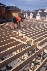
a) A floor with SPF SS 2×8 joists supports a 3 kN/m uniformly distributed factored load per joist with bending about the major axis. Determine the required bearing area (width and length) to adequately support the load (based on the joist only). The span is 20’.
Solution:
Cl. 6.5. 6.2 applies for compression resistance perpendicular to grain considering the effect of all applied loads. Determine the factored load. A 20’ span is 6.1 m. The bearing force is equal to the shear force at the ends of the joist:
![\[ Q_f = V_f = \frac{w_fL}{2} = \frac{3kN/m \times 6.1m}{2} = 9.15kN \]](https://ecampusontario.pressbooks.pub/app/uploads/quicklatex/quicklatex.com-aead829bf598985c1430cec86abd1ff9_l3.png "Rendered by QuickLaTeX.com")
Determine the strength for compression parallel to the grain:
fcp = 5.3 MPa (Table 6.4, Structural Joists and Planks)
KD = 1.0 (standard term, Cl. 5.3.2)
KScp = 1.0 (dry service condition, Table 6.10)
KT = 1.0 (no treatment, Table 6.11)
![\[F_c_p = f_c_p(K_D \times K_S_cp \times K_T) = 5.3 MPa \times 1 = 5.3 MPa\]](https://ecampusontario.pressbooks.pub/app/uploads/quicklatex/quicklatex.com-385eb75cb3aa38ea52debf4a27b84899_l3.png "Rendered by QuickLaTeX.com")
Determine the correction factors:
KB = 1.0 (load is applied at the end of the member, Table 6.16)
KZcp = 1.0 (the width is 38mm and depth is 184mm in this case, Table 6.15)
![\[Q_r = \phi \times F_c_p \times A_b \ times K_B \times K_z_c_p\]](https://ecampusontario.pressbooks.pub/app/uploads/quicklatex/quicklatex.com-e0f1a1dc113a35d6ef4f16c83c79f601_l3.png "Rendered by QuickLaTeX.com")
By setting the resistance equal to the factored load, the minimum length of bearing required can be calculated:
![\[ Q_f \leq Q_r \]](https://ecampusontario.pressbooks.pub/app/uploads/quicklatex/quicklatex.com-2921bde24e146b21c59d5fca5ad3d396_l3.png "Rendered by QuickLaTeX.com")
![\[9.15kN \leq 0.8 \times 5.3MPa \times 38mm∙L_b \times 1.0 \times 1.0\]](https://ecampusontario.pressbooks.pub/app/uploads/quicklatex/quicklatex.com-59e66b3ea4ed6c091a768fe289a21915_l3.png "Rendered by QuickLaTeX.com")
![\[Lb\geq56.8mm\]](https://ecampusontario.pressbooks.pub/app/uploads/quicklatex/quicklatex.com-a203dbe08f74a6e318902e11aa771790_l3.png "Rendered by QuickLaTeX.com")
Therefore, provide a bearing length of at least ~60 mm.
b) Consider a SPF-No. 1 6×10 beam subjected to 10 kN point loads at 0.5 m increments over the length. Each 10 kN load is applied over a 50 mm length of the beam. The beam rests in a 100 mm hanger. Check if the bearing capacity is adequate for the 10 kN load applied near the support.
Solution:
This situation falls under Cl. 6.5.6.3 since it is considering a load (10 kN) applied near the support. Thus, both Cl. 6.5.6.2 and Cl. 6.5.6.3 need to be checked. This example will focus on the latter clause only.
The 6 x 10 (140 x 241 mm) will only have one point load applied within a distance of d = 241 mm from the end. It is assumed that the beam is subjected to bending about the major axis (typical).
Determine the strength for compression parallel to the grain:
fcp = 5.3 MPa (Table 6.6, Beam and Stringer)
KD = 1.0 (Standard Term, Cl. 5.3.2)
KScp = 1.0 (Dry Service Condition, Table 6.10)
KT = 1.0 (No Treatment, Table 6.11)
![\[F_c_p=f_c_p(K_DK_S_c_pK_T)=5.3 MPa \times 1 = 5.3MPa\]](https://ecampusontario.pressbooks.pub/app/uploads/quicklatex/quicklatex.com-48cf82f4e6549ceb4cb38e78e5804479_l3.png "Rendered by QuickLaTeX.com")
Determine the correction factors:
Determine the average bearing area (Cl. 6.5.6.3.2):
![\[A′_b= b\frac{L_b_1 + L_b_2}{2} \leq 1.5b(L_b_1)\]](https://ecampusontario.pressbooks.pub/app/uploads/quicklatex/quicklatex.com-b7a9b7e74df3a705874e9b6086aa5b0c_l3.png "Rendered by QuickLaTeX.com")
![\[A′_b= 140mm \frac {50mm+100mm}{2} \leq 1.5 \times 140 mm \times 50 mm\]](https://ecampusontario.pressbooks.pub/app/uploads/quicklatex/quicklatex.com-2f142031f5bd62c7417916352164fcc0_l3.png "Rendered by QuickLaTeX.com")
![\[A′_b= 10,500mm^2 \leq 10,500 mm^2\]](https://ecampusontario.pressbooks.pub/app/uploads/quicklatex/quicklatex.com-de46dacf8732ee8f8e45b194d6b8e48e_l3.png "Rendered by QuickLaTeX.com")
Therefore:
![\[Q′_r=\frac{2}{3} \times φ \ times F_c_p \timesA′_b \times K_B \times K_Z_c_p\]](https://ecampusontario.pressbooks.pub/app/uploads/quicklatex/quicklatex.com-a581b0a72dcd732a69aa83e703c4786f_l3.png "Rendered by QuickLaTeX.com")
![\[Q'_r=23 /times 0.8 /times 5.3MPa /times 10,500mm^2 /times 1.0 /times 1.0 /times\]](https://ecampusontario.pressbooks.pub/app/uploads/quicklatex/quicklatex.com-45b53f518d9d34b02d65cbd12aa57f99_l3.png "Rendered by QuickLaTeX.com")
![\[Q'_r=29.7 kN\]](https://ecampusontario.pressbooks.pub/app/uploads/quicklatex/quicklatex.com-aa753090f106ac89d90904bd94ed02b1_l3.png "Rendered by QuickLaTeX.com")
Therefore, the bearing resistance is 29.7 kN which exceeds the 10 kN applied load; the design is acceptable.
c) What is the bearing capacity of a 38 mm x 114 mm Northern SS member supported along the 114 mm width? The length of bearing is 50 mm. Use design aids.
Solution:
This situation satisfies all the conditions in the checklist on Pg. 327 except for KZcp. Since the width is 114 mm and the depth is 38 mm the ratio is over 2. Thus, we can use KZcp = 1.15.
Using the design tables on Pg. 333, the resistance is:
![\[Q_r=q_rl_bK_Z_c_p=0.319kN/mm \times 50mm \times 1.15 = 18.3kN\]](https://ecampusontario.pressbooks.pub/app/uploads/quicklatex/quicklatex.com-736b8a8ead4db1ac09000ce0922bb819_l3.png "Rendered by QuickLaTeX.com")
Therefore, the bearing resistance is 18.3 kN.
d) What are the components of a stud wall? What checks need to be completed to determine the gravity force carrying capacity? Are there design aids for stud walls?
Explanation:
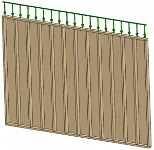
A stud wall is composed of top and bottom plates, studs, and sheathing. When resisting gravity loads, the top and bottom plate are subjected to compression perpendicular to the grain, whereas the studs are subjected to compression parallel to grain. The sheathing generally braces the minor axis of the studs from buckling.
Design aids for stud walls are provided; the checklist is on Pg. 157. The tables begin on Pg. 163. Note the bearing capacity is provided at the bottom of the table. Note that these bearing capacities assume KB = 1.25 and KZcp = 1.15.
