20 Drawing Type | Design Concept: Axonometrics
michealg1
Axonometric Intro
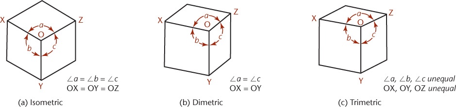
An axonometric view is the drawing of an object where the viewer can see all three sides of the object without taking into account perspective foreshortening. This is done by rotating the object or set of objects along one or more axes relative to the viewer. Within axonometric projections are different standard perspectives based on the orientation of the view. We will be focusing on using the Isometric point of view where all angles of our forms are equal.
The purpose of creating such diagrams in urban design is to create clarity in our analysis and proposal. By eliminating perspective and simplifying our urban forms into recognizable categories, we can more effectively communicate with our viewers.
Urban Context SKP Download
I will be focusing my axonometric around the Bramm Yards in Kitchener. We must first download our urban context to begin working on our axonometric. To do this, head to CADMAPPER to download an SKP file of our urban context. When making a new map, your screen should look something like the following:
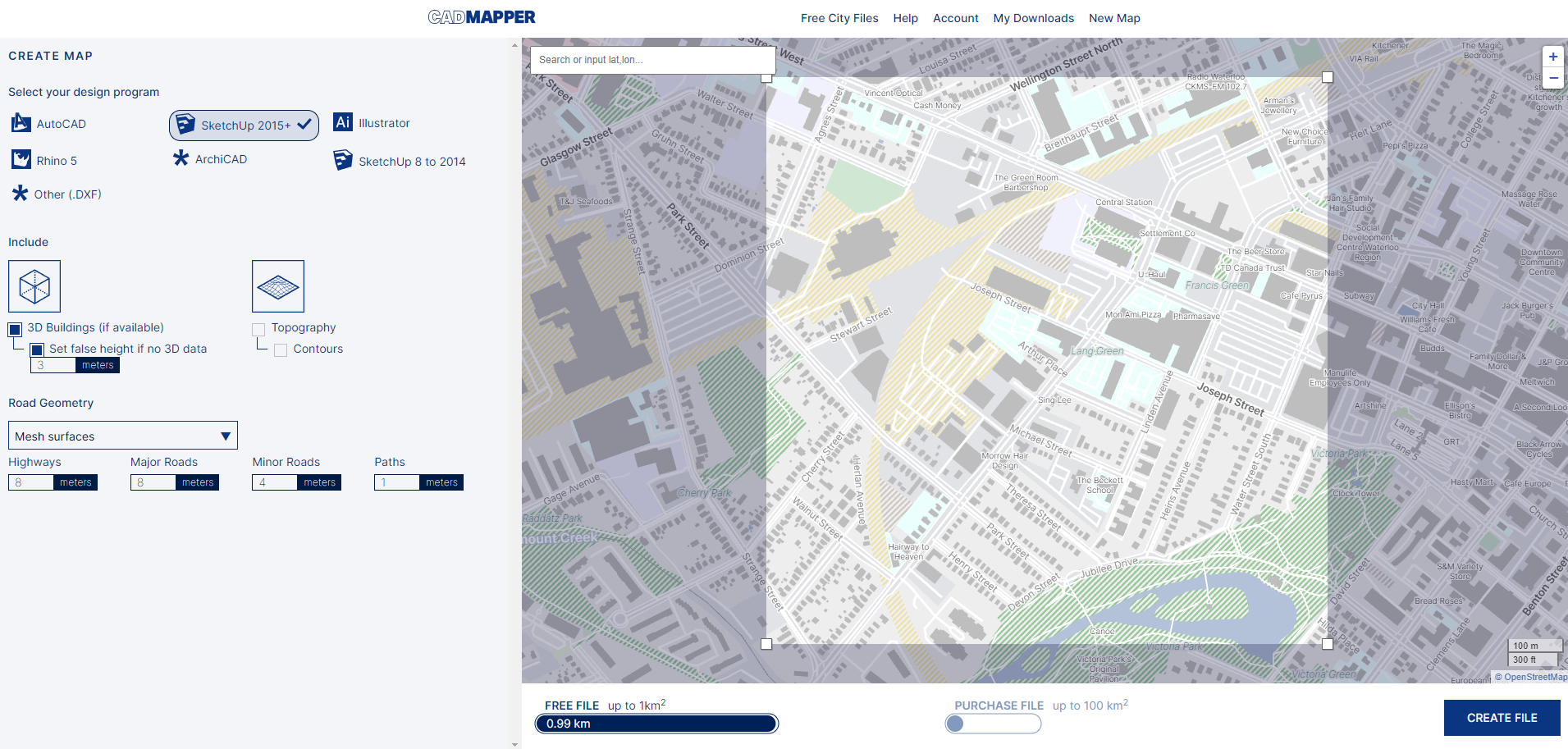
As displayed above, I recommend making sure that you “Set false height if no 3D data” as 3 meters in case some buildings do not have a massing. For this turorial, we will be setting the “Road Geometry” to “Mesh surfaces”. I have “Major Roads” denoted as being 8 meters, “Minor Roads” as 4 meters, and “Paths” as 1 meter. Once you are happy with your extent and settings, click the “CREATE FILE” option at the bottom right. You should be presented with the following preview menu:
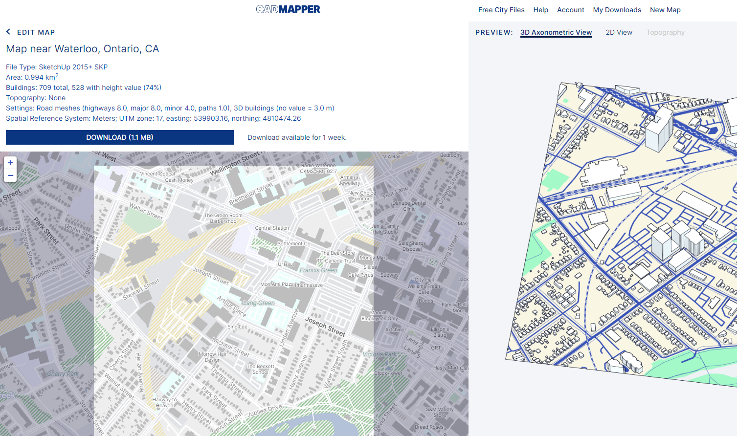
From here, we download the actual SKP file. Press the “DOWNLOAD” option. You will download a ZIP file which you will have to extract prior to importing the file into Sketchup.
Importing & Setting Up Sketchup
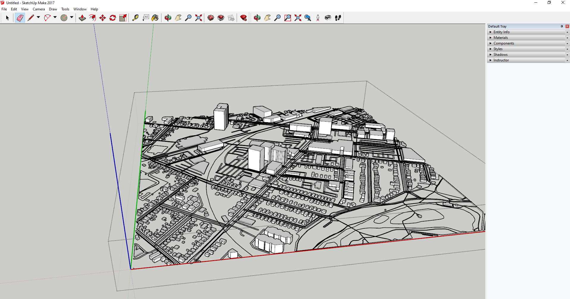
To import the downloaded SKP file into SketchUp, you can simply drag and drop the file into a new Sketchup project. After importing, feel free to scale the model to suit your preferences. This is what my SketchUp preview looks like:
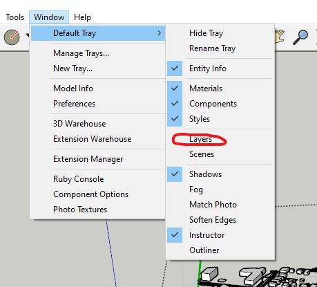
Next, we want to make sure that we are able to access our layers within SketchUp. To make sure your layers options are available, select the “Windows” option from the top options, select “Default Tray”, and make sure that your “Layers” option is selected.
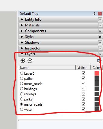
 Confirm that your “Layers” panel is visible on your” default tray on the right-hand side:
File Cleanup
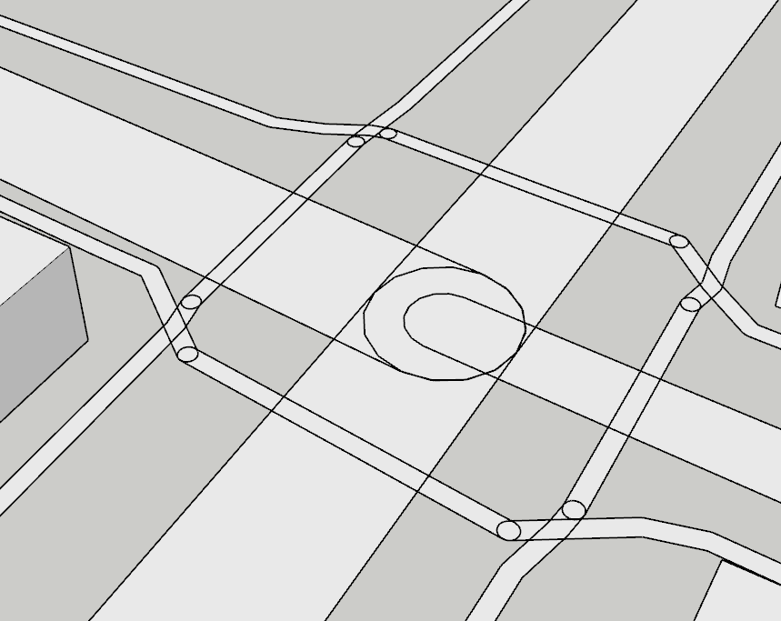
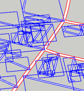
A problem that we want to fix has to do with the minor roads, major roads, and paths. The issue is that the faces of each road are seperate and display outlines that will be apparent on our axonometric if they are not dealt with. Example:
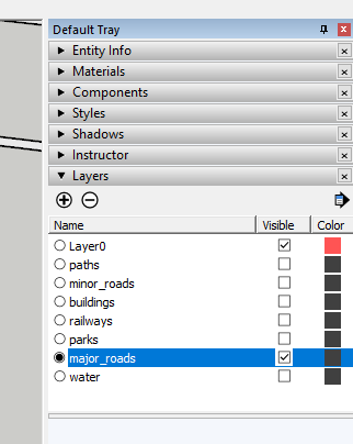
To begin, we must first hide all other layers aside from the “major_roads” layer. This can be done in our “Layers” panel. By clicking the visibility option, we can hide that specific layer. This is what your layers panel should look like:
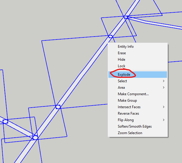
 Next, we want to select every element in our only visible layer (major_roads), right-click, and select the “explode” option. We do this because currently, each element is in its own group. After exploding, each element will be ungrouped and be a more flush surface.
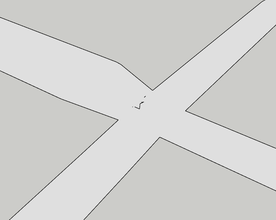
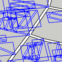
Exploding the groups is a quick and easy solution but is not perfect. Technically, the surface is not one entity but for the purpose of this tutorial, it is good enough. We do need to do a little bit more cleaning up. As you can see in the following image, there are still some line artifacts that need to be erased:
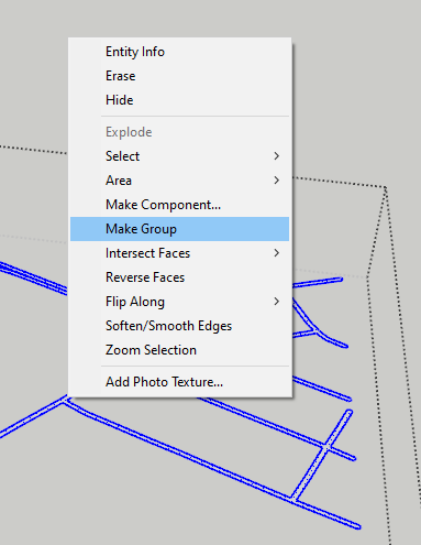
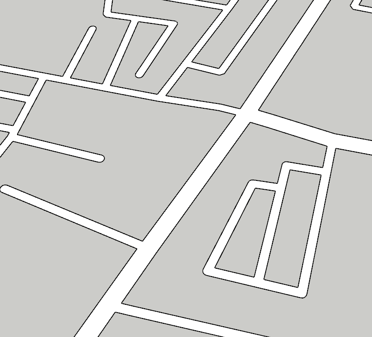
 Use the eraser tool to further clean up our file. We want to make the road into a group to make it easier to work with. Do this, right-click after selecting every element in the current layer and choose the “Make Group” option.
After making the group, lock the group:
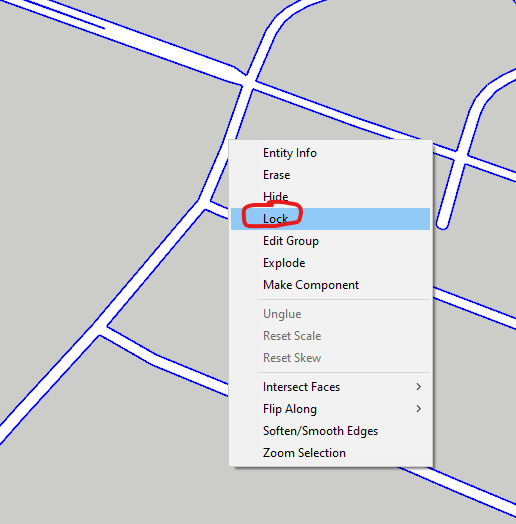
We are locking the group to avoid crashing the program after exploding every element. Next, we are going to keep the “major_roads” layer open but now also make the “minor_roads” layer visible. we will select everything again and deselect our “major_road” (outlined in red by holding SHIFT and left clicking on the element to remove it from the selection (before/after):
We will be exploding our selection again. Next, we want to select our “major_roads” locked group layer. Unlock the entity, and explode it after right-clicking it. This will merge the minor and major roads. Example:
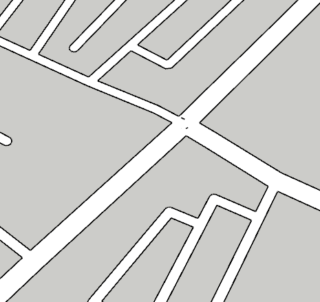
Again, erase artifacts that appear as a result of the merge. Example:
Classifying Elements (optional)
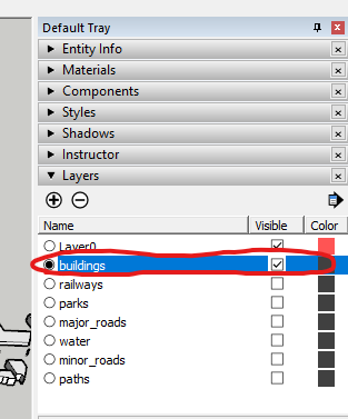
For our next step, we will be classifying our buildings with different colours. This is an optional step depending on the purpose of the analysis. To begin, make sure only your “buildings” layer is visible:
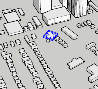
Next, we want to make sure that we are within our buildings group and not the broader city group. Double click on a building until you only have one building selected:
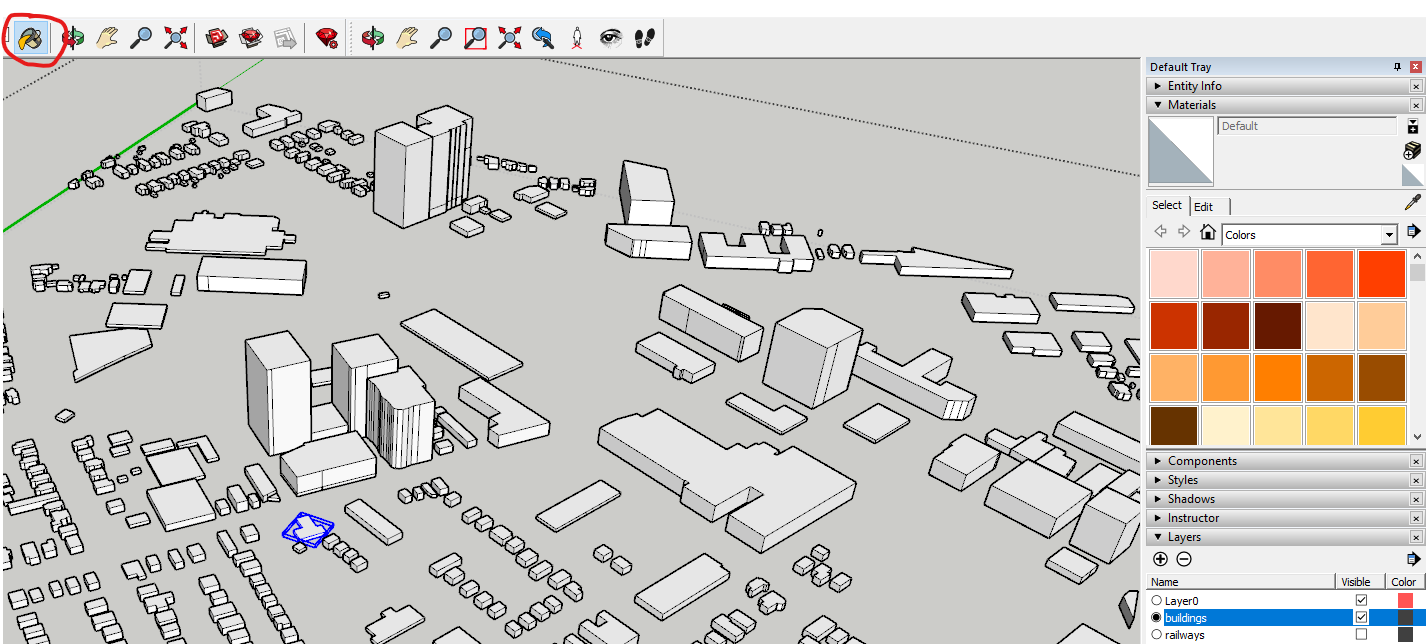
 Using the “Paint Bucket” tool, we can select a colour and paint our buildings or whatever elements we choose to denote:
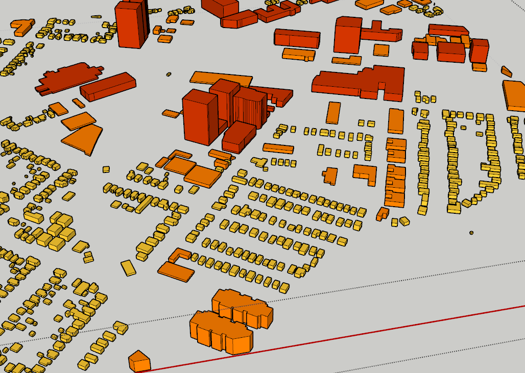
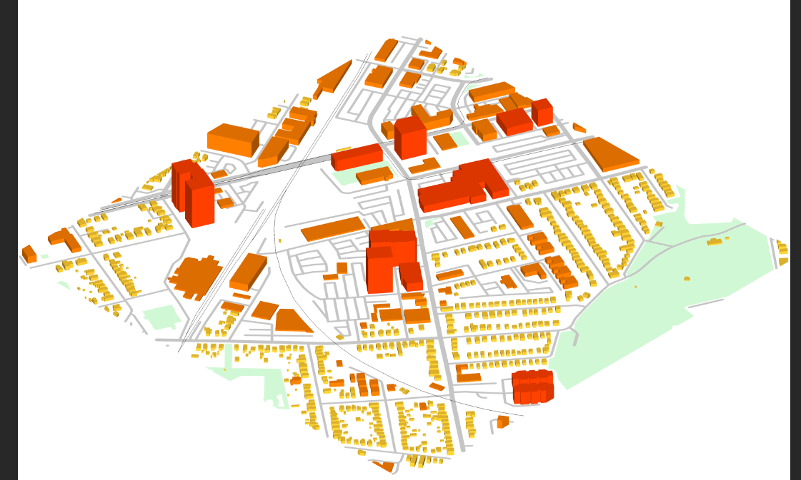
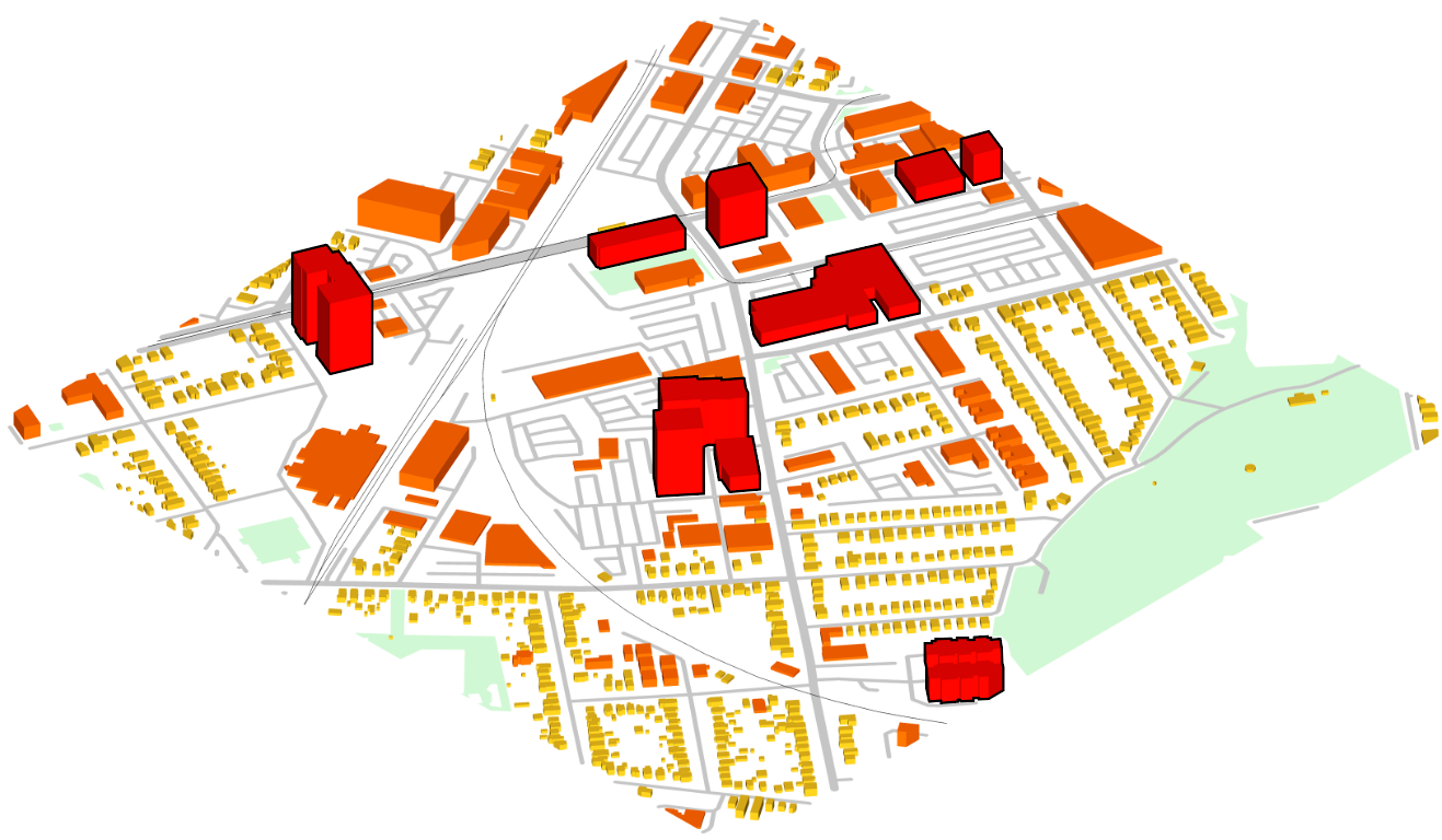
 I arbitrarily chose to classify my buildings based on how intensive the building massing seemed. This is what my classified buildings look like:
TIP: you can drag to select multiple objects with the “Select” tool and switch to the “Paint Bucket” tool to colour a large number of objects at once.
Isometric Axonometric View
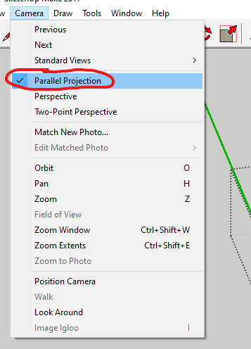
To view your model from an isometric axonometric view, select the “Camera” dropdown menu and select “Parallel Projection”:
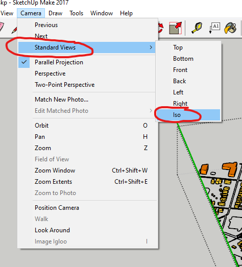
Then select the “Camera” drop-down menu, “Standard Views”, and “Iso”:
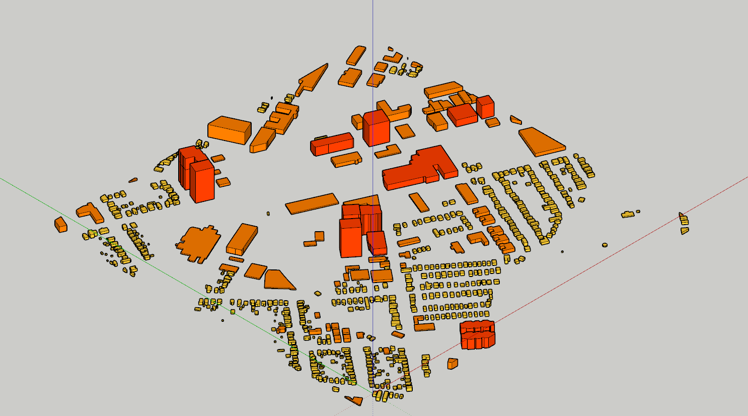
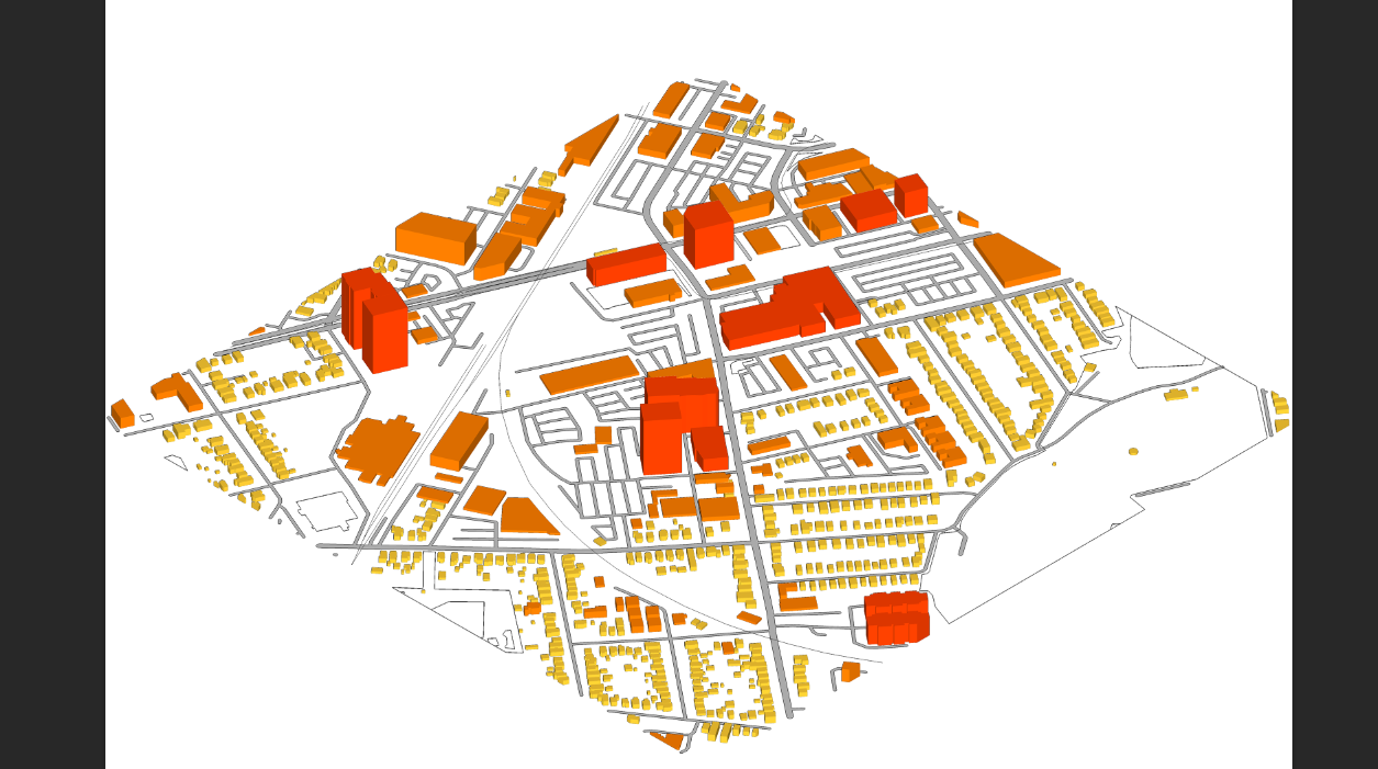
 The orientation that the camera takes is dependent on the original position that you take and the distance of your camera from the model so repeat the above steps until you have a view that you are happy with after reorientating your camera and trying again. This is what my isometric view looks like:
Exporting Components
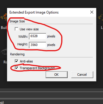
We will be exporting components separately to make post-processing and the following chapter for exploded axonometrics easier. To begin, we will be turning each layer off and exporting each layer one by one. To begin, I will be exporting the “buildings” layer first. To export, select the “File” dropdown menu, select “Export”, and click “2D Graphic”. Prior to hitting “Export” you need to make sure that in your “Options” menu that the “Transparent Background” option is turned on. Additionally, we want to have the highest quality of images to work with. I will be increasing the size of my image export 4x larger than the default option:
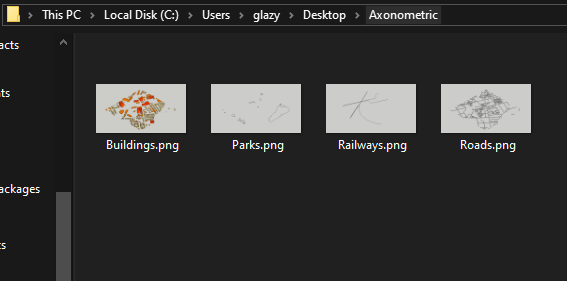
Re-do this step until you have exported “buildings”, “parks”, “railways”, and any other layer that you wish to also include in the final presentation. When exporting the minor and major roads, make sure both are visible as we will be treating both of these layers as one. This is what my download folder looks like:
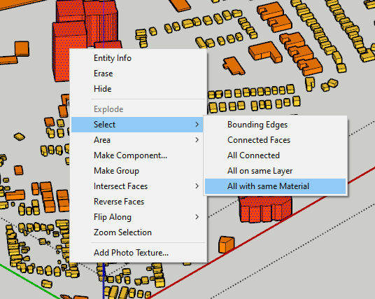
We also wish to export each of our categorized building groups. To do this, explode everything in the “buildings’ layer similar to previously before. Next, using the “select” tool, right-click on one of your buildings and click the “Select” option, and then choose the “All with same Material” option. This should select all of the buildings with the same colour. I am purposfully only selecting the faces without the accompanying edges. If you wish to also export the building edges, you can use the same directory but also select “Bounded Edges”. This will select both the faces and the edges of the buildings.
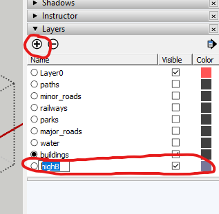
To effectively separate and later hide the buildings, we want to move this selection into a new layer. To create a new layer, there is a “+” symbol in the “Layers” tray. Clicking it will create a new layer for you to rename. I will be renaming my new layer to “highB”:
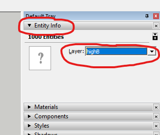
 To move your selection into the new layer, open the “Entity Info” tray and select the new layer that you created in the dropdown menu:
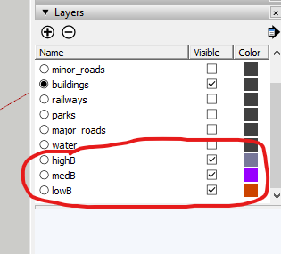
 Repeat this process until all of your building groups are in their own layer. This is what my “Layers” tray looks like:
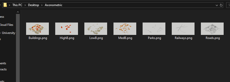
Similar to what has already been described, export each new layer we created separately. Make sure you did not move your camera at any point in this process as the exports will not line up. This is what my export folder looks like now:
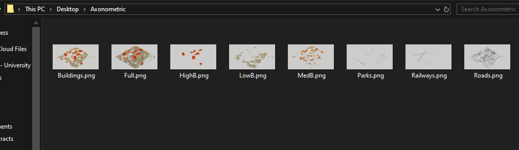
Turn on all of the layers that you will be exporting and create a full export of all of your layers on top of each other. This is what my final folder looks like now:
Post Processing in Photoshop
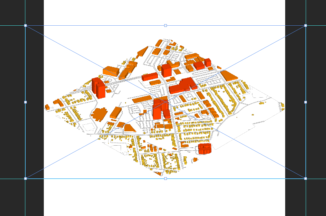
Though we already have a decent isometric just from the SketchUp export, we are going to make it look a little bit more professional in Photoshop and Illustrator. Within Photoshop, create a new file that is decently sized (mine is 10.8 x 10.8 inches). We will start off by dragging and dropping the layer with all of our elements. Transform the element until it fits onto the canvas by using the shortcut CTRL + T and dragging the corners while holding SHIFT until it is to your liking. Make sure that your image is centred:
While using the shortcut CTRL + T, drag guides from the rulers located on the edges of the canvas preview onto each edge of your image. If you do not see the rulers, press the CTRL + R shortcut to enable them. This is what my guides look like:
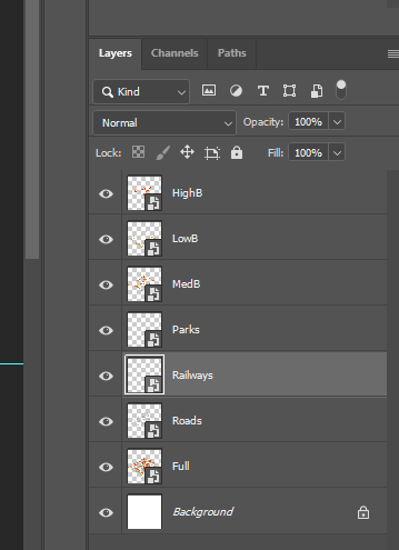
Drag in your separate elements now on top of your complete image (buildings, rail, streets, etc.). Use the guides to appropriately reside all of your imports. Rearrange the hierarchy of the layers so that the elements overlap appropriately. This is what your layers panel should look like after importing all of your elements:
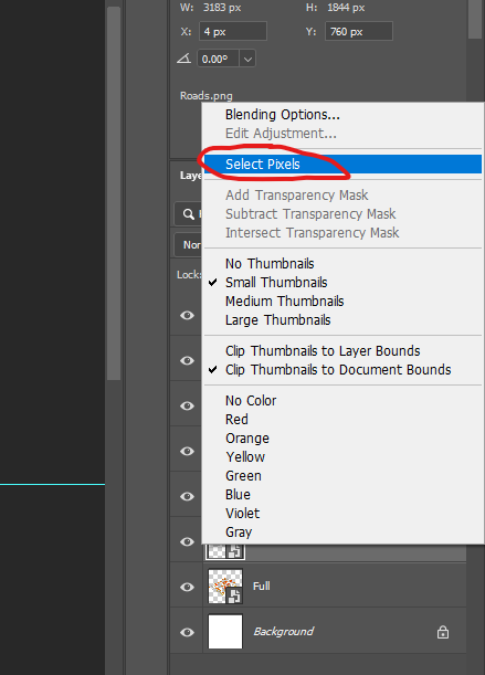
We are going to make the roads a little more cleaner. Select the road pixels by right-clicking on the “Roads” layer square icon and choose “Select Pixels”:
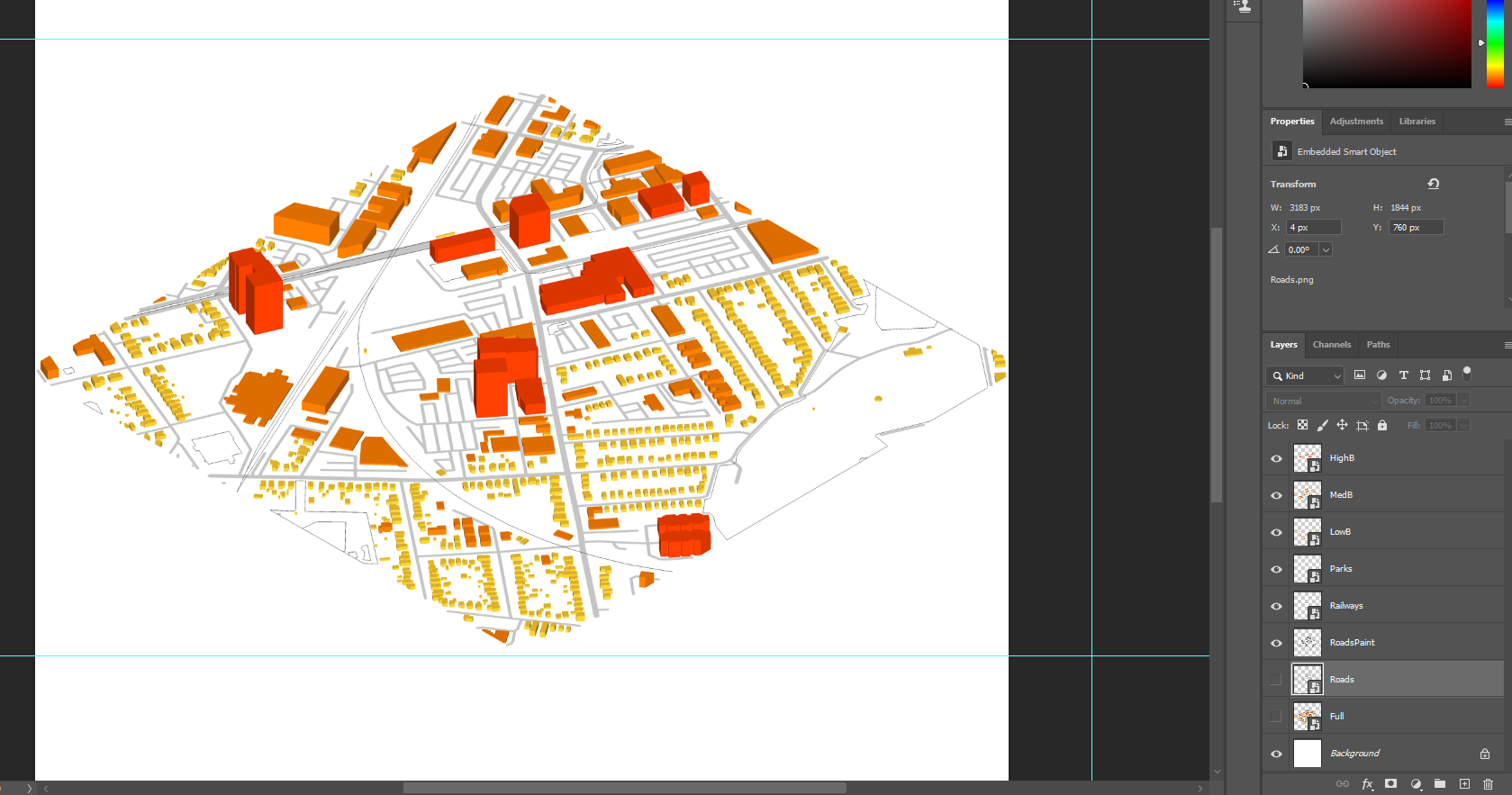
This will create a selection that you can fill with colour. Using the “Brush tool”, I filled in the selection with black and turned down the opacity. You will notice that a new layer has been created, I renamed this new layer to “RoadsPaint”. When you are done filling in the selection, feel free to turn off the “Roads” layer, and “Full layer”:
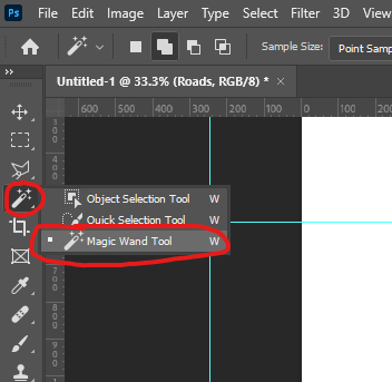
Next we want to colour our “Parks” space. To do this, turn off the visibility of every other layer other than “Parks”. To begin, select the “Magic Want Tool” and click on the greenspaces that are denoted in the “Parks” layer to create a selection.
Similar to the roads, we will be painting in the greenspace using the “Brush tool”. This is what my greenspace looks like after turning on the visibility of my layers again:
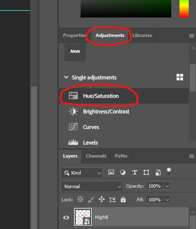
This next step is optional. If you do not like the the current colour or anything to do with how the buildings look like, we are able to clip adjustment layers to change their appearance. Starting with the HighB layer, we will go into the “Adjustments” tray and choose the “Hue/Saturation” option:
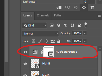
 This will create a new adjustment layer in your “Layers” tray you can choose what to adjust when you select the adjustment layer and change its properties in the “Properties Panel”:
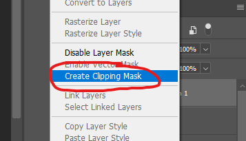
To make it a clipping mask and make the adjustment layer only apply to one particular layer, right-click the adjustment layer and select the “Create Clipping Mask” option:
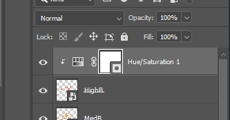
Your adjustment layer should look like this in your “Layers” tray:
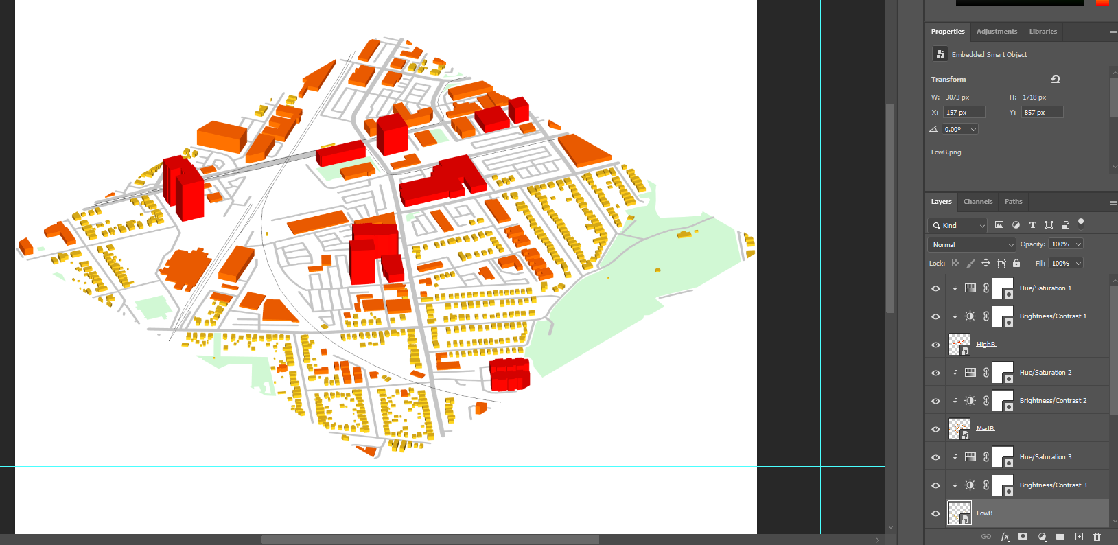
The adjustment layer will now only apply to the layer below it. You can reorder your layers and clipping masks to apply adjustments as you see fit. This is what my preview and layers look like:
We can export it as a PNG as a final version or take it into Illustrator to add some extra details.
Post Processing In Illustrator
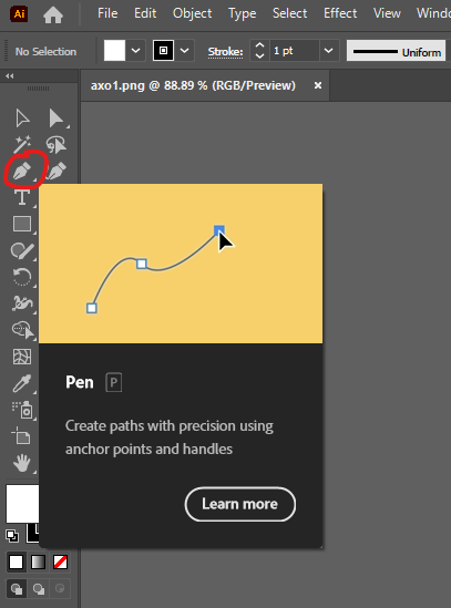
Drag and drop your PNG export from Photoshop into Illustrator. I wish to highlight the red buildings to give them more emphasis. To do this, select the “Pen” tool and outline the buildings:
 This is what my outlined buildings look like:
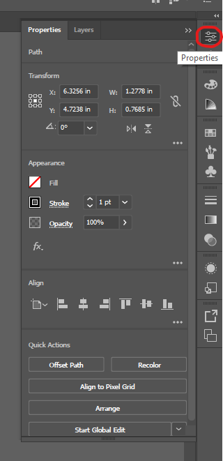
You can change the properties of the lines in the “Properties” panel from the right-hand tray:
 Feel free to export after outlining your elements or adding anything else.
Discussion
I went over how to make a basic axonometric. The most crucial part of this activity was understanding why we needed to separate our elements after exporting in SketchUp. Separating the elements allows us to work within the layer non-destructively and easily change aspects of certain elements with ease and speed. Apply the concepts within this chapter and previous chapters, it is obvious that the options are limitless with how you choose to display and axonometric. I would encourage you to render the SketchUp file in a rendering software before the post-processing stage to make your elements look the highest of quality.

Author: Micheal Glazyrin
