16 Technique: Digital Modelling with SketchUp
Learning Objectives
- Trace the air photos,
- Explore Sketchup features
- Import components from 3D Warehouse
- Create a site plan document using LayOut
- Explore some features of LayOut
- Learn how to do 3D extrusions in SketchUp
- Create features 3D located on your site
- Learn SketchUp tools: Follow Me, Scale, Push and Pull
Keywords:
- 3D Model; SketchUp; CAD Mapper
Introduction to Sketchup
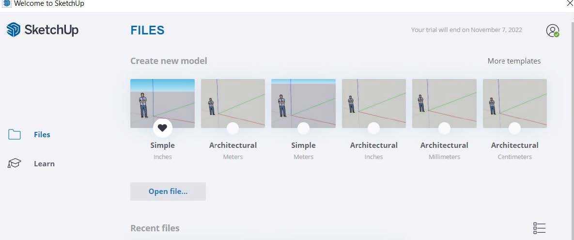
Launch SketchUp from the apps on the “dock”/taskbar and open a blank project.
Select architecture; meters
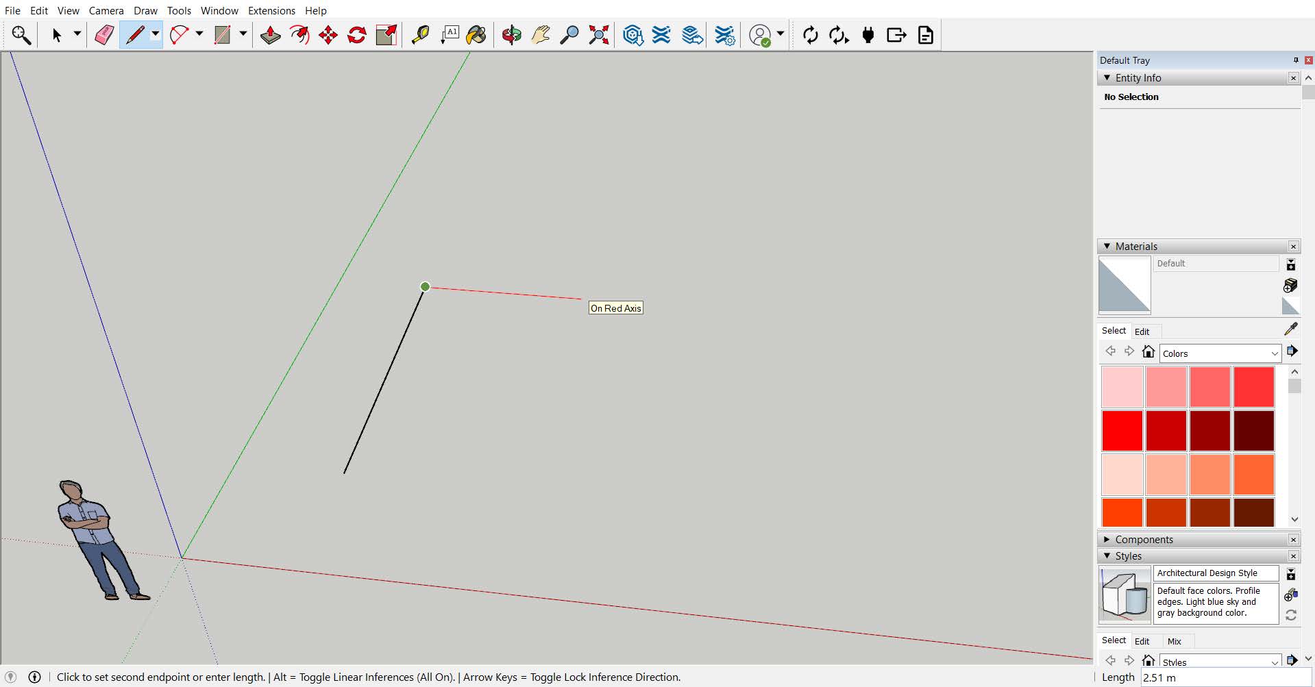 Select the line tool in the top bar (or press shortcut key “L”). Spend some time (~10 mins) exploring the tool and the interface by drawing different shapes and forms.
Tip: To draw lines more freely, you can turn off the “axis snapping” by pressing the Command key (alt for windows). You’ll see it indicated at the bottom left of the screen when you start moving the cursor after setting the first point. This will be useful later when tracing the air photo.
Once you have explored drawing with the line tool, you try out the circle tool, arc drawing tools. Move onto the offset and move tools. You can close the file without saving.
Download the Skp. file of your selected case study park/square from LEARN.
When you open the file, You’ll find the air photo to trace, and the buildings showing the urban context.
For Waterloo square, in addition to these a hidden view of the semi-completed model of the elevated platform, with ramp and stairs are included.
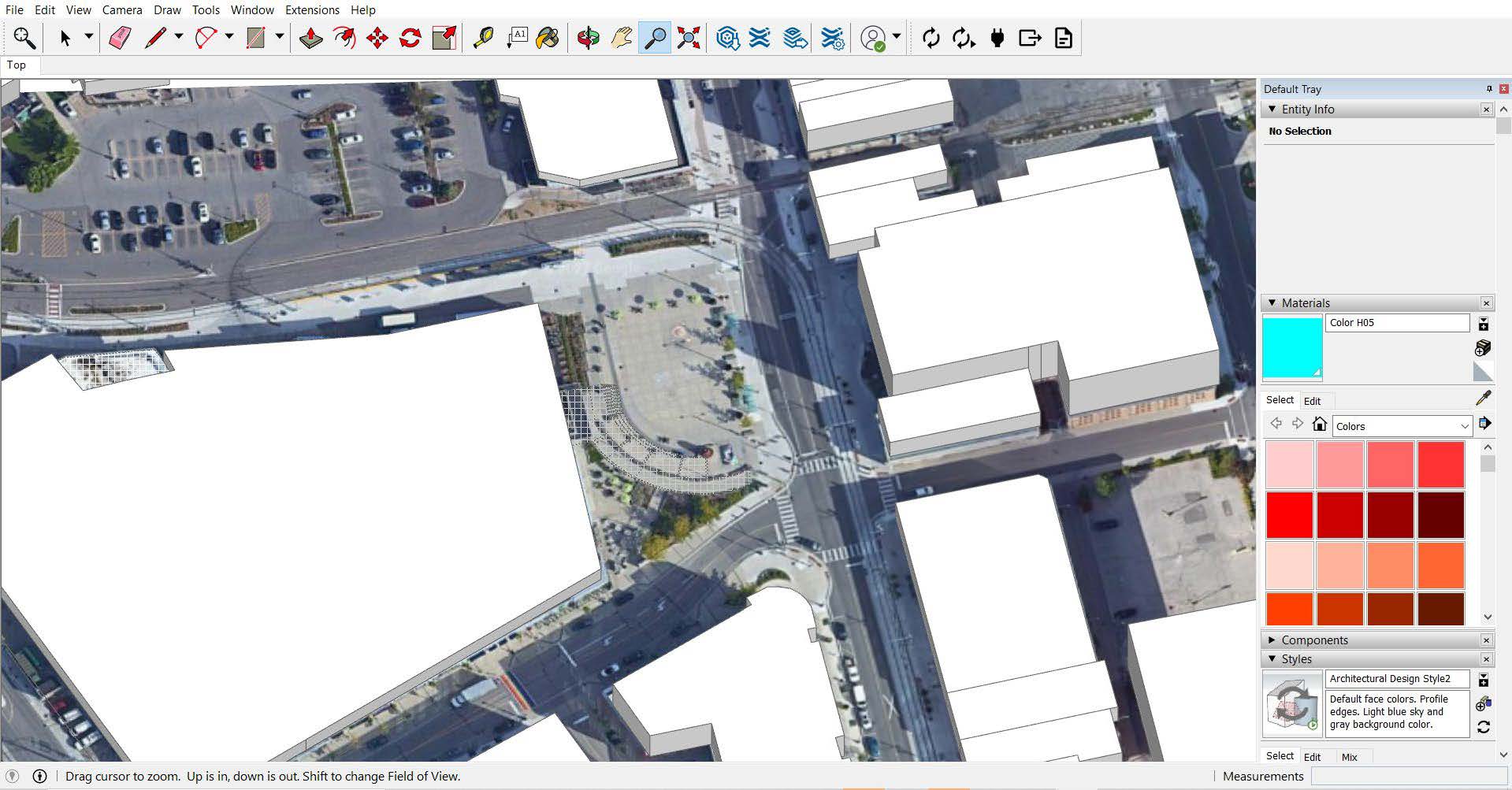
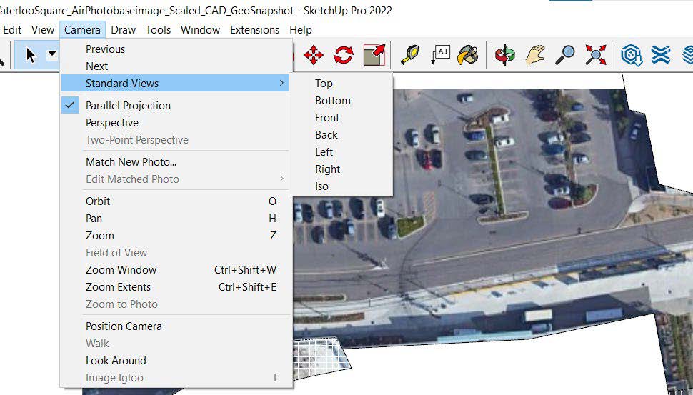
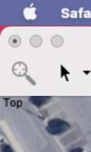
Go to the Camera tab and see all the various ways to view the model. A plan view is looking down from above, so you will work in “top” view.
Uncheck “perspective” and pick parallel projection for now.
Note shortcut tools for orbit, pan, zoom. Orbit is key for working in 3D.
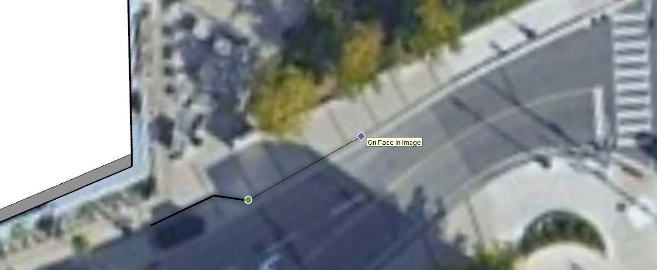
With the line tool, start tracing the site boundary on the air photo. You can also use google earth/maps and street view to assist you with more visuals.
As mentioned earlier, you can turn off the “axis snapping” by pressing the Alt/Command key. You’ll see it indicated at the bottom left of the screen when you start moving the cursor after setting the first point.
Make sure you are drawing on the same level directly on the face of the photo.
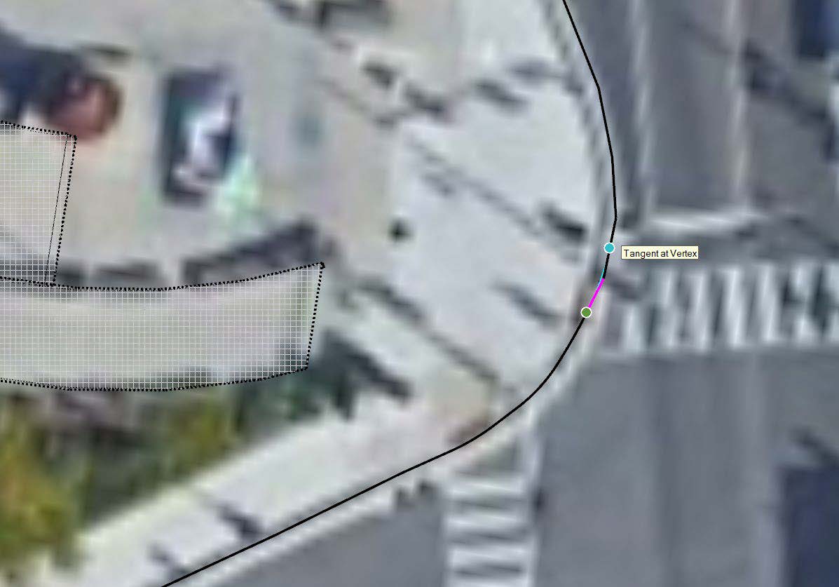
 Use the Arc tool (shortcut “A”) to smooth out curb lines and curved surfaces.
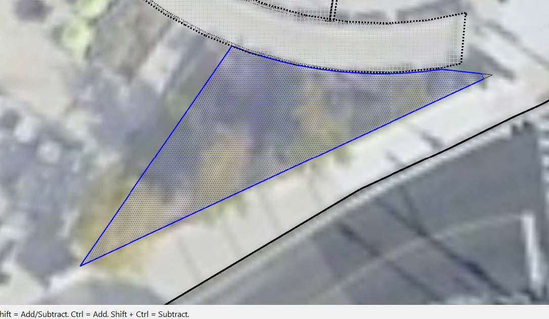
You will click on each end of the arch (aqua and green lines shown) then move your mouse to get the arc at the correct radius.
You will click on each end of the arch (aqua and green lines shown) then move your mouse to get the arc at the correct radius. When adding new line segments, be sure to click on the end of your last segment so that they join properly. Use the eraser to remove any rough ends.
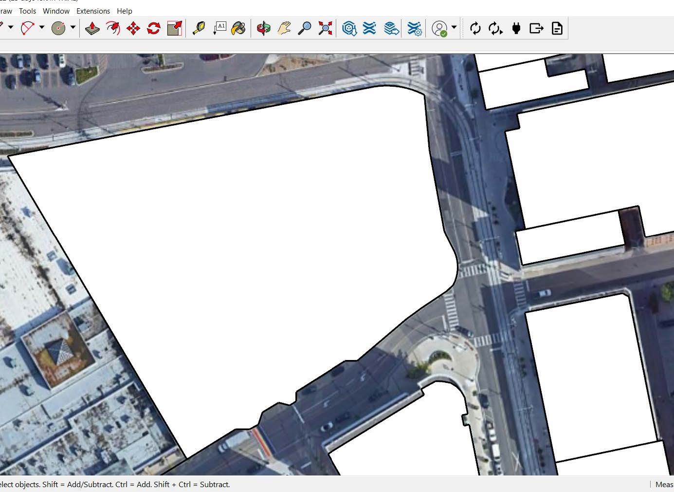
When you are done, you should have a closed polygon shape, with a surface generated.
If you don’t get a closed polygon, there’s a break somewhere in your tracing and you will need to correct any past segments to make sure your line segments are connected.
The circle and offset tool will be helpful for creating the pavings, seating areas and pathways.
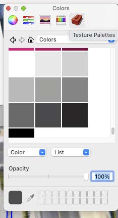
Press “B” on your keyboard to use the Paint Bucket tool. The Materials panel will appear. Click on “Texture Palettes” and select “Colors” from the drop-down menu, scroll down to the bottom of the list and choose any grey scale color.
To continue tracing, we need to decrease the opacity of the selected material. Change the opacity to 40%.
You can now paint the newly generated surface by clicking on it. Feel free to lower the opacity if needed.
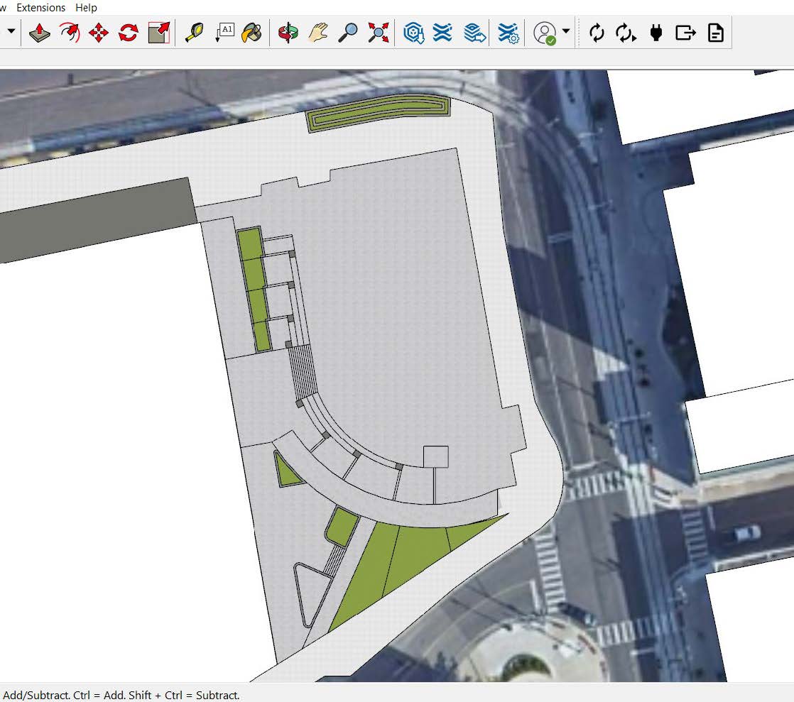
Continue tracing all other surfaces inside the site. Make sure your lines are creating closed loops and surfaces are generated. To check this, click inside the shape and see if it is highlighted/shaded.
You can paint finished surfaces with materials as you go.
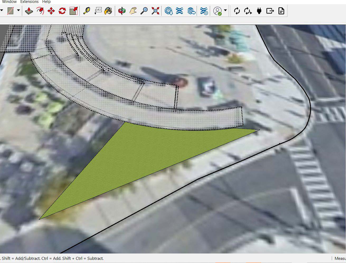
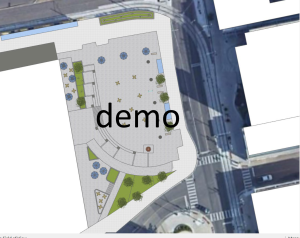
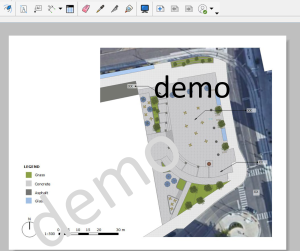
Once done tracing and painting the surfaces, your site plan would look like this:
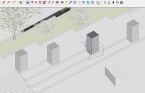
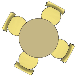
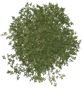
Your plan needs the components that exist on the site such as trees, street furniture, streetlamps, benches, tables and chairs, playgrounds.
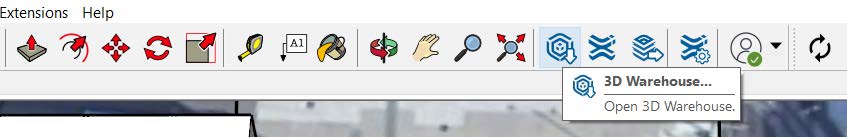
On the top bar, click on 3D Warehouse. You will be asked to sign in. You can create a Trimble ID from the Sign In window if you don’t already have one.
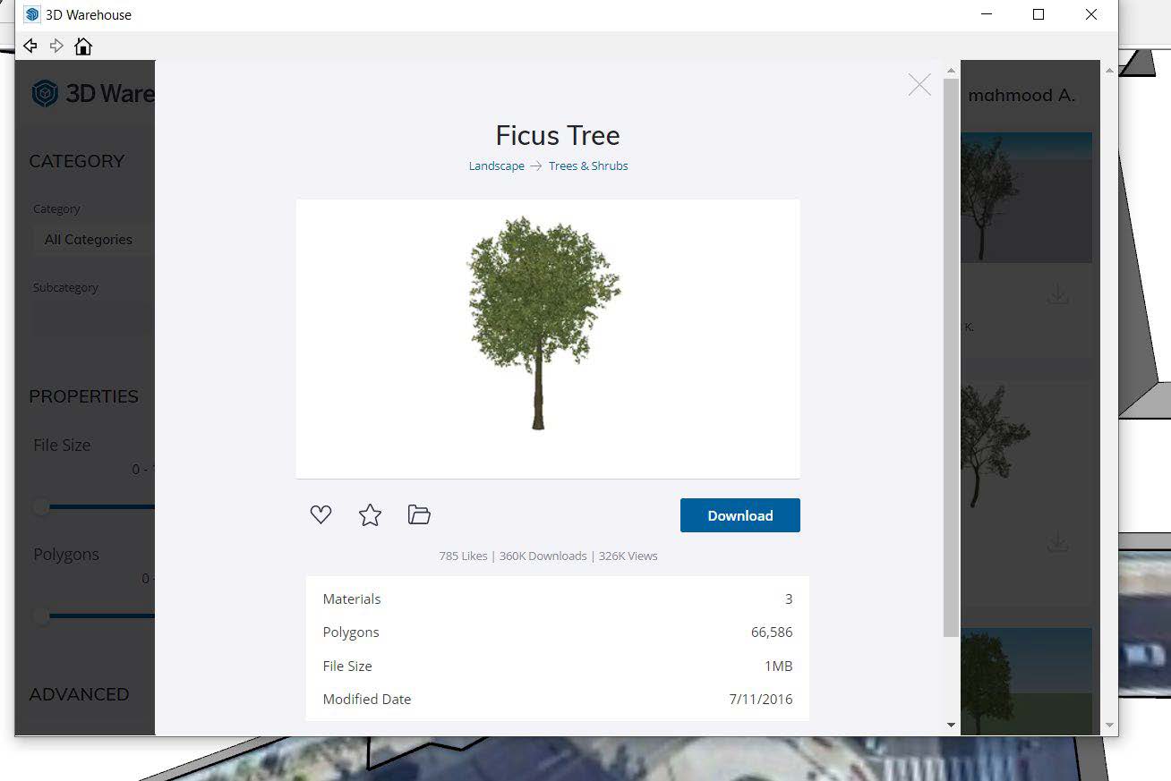
Search for components in the search bar. In general, the smaller file size and lower number of polygons in the component, the more your SketchUp file can run smoothly.
Click on Download and pick a point on your site to place it. Feel free to edit their materials/colors to better match your context.
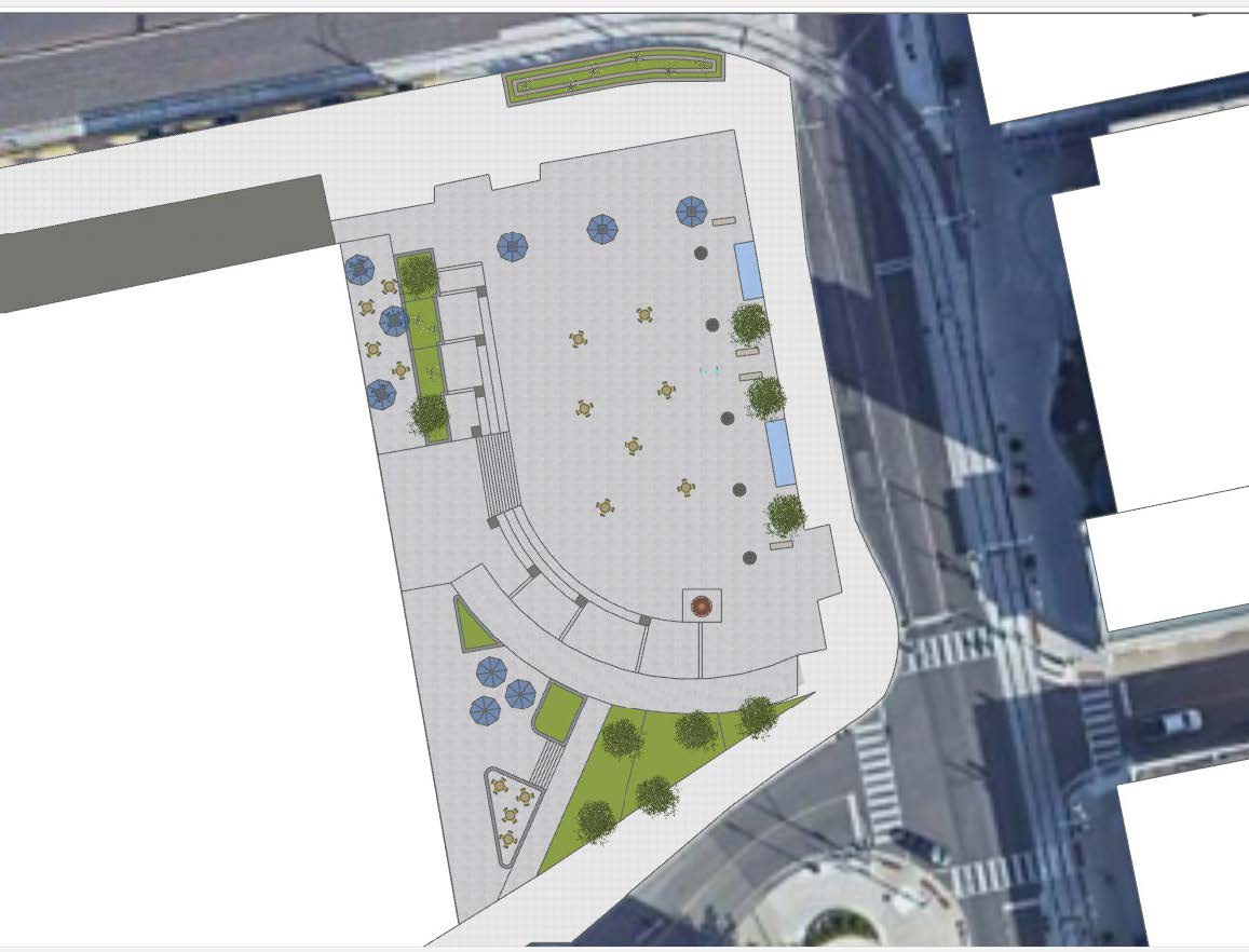
The site plan with the components would be like this:
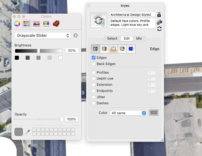
If you like to make your line weights lighter, you can do that by going to Window in the top bar and click on Styles. The Styles panel will appear. Click on Edit>Edge>uncheck everything except “Edges”.
Additionally, you can also change outline colors. On the bottom, go to color, click on the color rectangle. Go to the Grayscale Slider and change the Brightness level to 50%. This will change the outlines to a lighter grey.
Introduction to LayOut
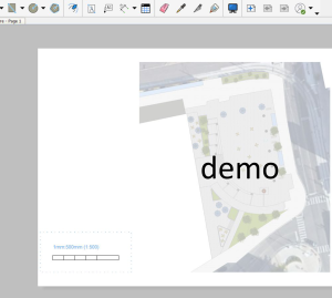
Before exporting to LayOut, we need to set a 2Dplanview of the site. On the top bar, go to Camera>Standard Views>Top. Now we should set it to 2D view. Again, go to Camera and make sure that Parallel Projection is checked. You should now see the word “Top” on the top left corner of your screen.
Zoom into show your full site and use the Pan tool (shortcut Command + R) to center your site on screen. You may want to avoid using the Orbit tool as it would exit the top view. Make sure that “Top” is still visible in the top left corner.
Now we need to save this view by adding a Scene. On the top bar, go to View>Animation>Add Scene>Save as a new style>Create Scene.
Now you will see Scene 1 below the top toolbar. Right click on Scene 1 and click on Rename and type “Plan View”, press Enter.
Save your file.
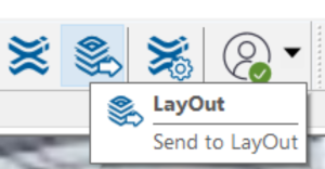
To export to LayOut, go to the top toolbar and click on LayOut.
A template window will pop up. Click on “More templates” in the top right corner. Under Plain Paper category, choose Letter Landscape.
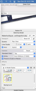
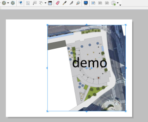
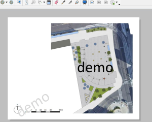
You should now see a viewport showing your site. If your site is not centered. Double click on the viewport. Press and hold the shift key while holding down your mouse wheel to Pan around until the site is entirely visible and centered. Once done hit the Space bar. Click on the site once. Go to the panel on the right side. Under Sketchup Model, make sure that Ortho and Preserve Scale on Resize are checked, and that Standard View is Top. Change the scale to (1:500).
Now you can adjust the viewport boundary by dragging the blue arrows in the corners. The plan should show the full site with the adjacent streets.
We should now draw the scalebar. With your viewport unselected, go to the right panel, under Scaled Drawing, set length as Decimal, Millimeter, and set scale to (1:500)
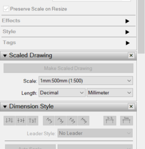
Click on the Line tool in the top toolbar. Start drawing a line by placing your first point.
Move your cursor horizontally to the right, type 5000 on your keyboard, and hit Enter. Repeat this process until you get a total of 6 segments.
5000 indicates 5000mm (or 5m) on site. This means that every 10mm (1cm) on paper is equal to5m on site.
At the last segment, move your cursor vertically downwards and type 1000, and hit Enter. This will be the width of your scale bar.
Close the shape to form a rectangle.
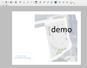
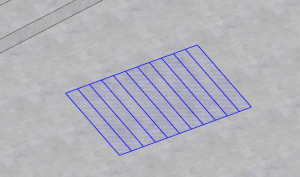
Draw vertical lines at each endpoint except the last one as shown in the image below.
Once completed the scale bar, press the Escape key.

Use the Rectangle tool from the top toolbar to draw one rectangle on the first segment and fill it with black.
Click on the rectangle, hold the Option key, and drag the rectangle from one of its corners to the third and fifth segments. The last rectangle can be resized by moving the blue arrows as shown in the image.
Use the Text tool to add number to the scalebar.
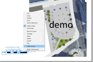
Select the scale bar and the numbers, then right click, and select Make Group.
Use the Circle and Line tools to draw the North sign. The line weight could be modified by going to the right panel under Shape Style and changing the stroke weight.
Remember to make the North sign as group.
Lock your viewport by right clicking on it and select Lock from the menu.
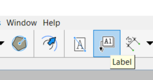
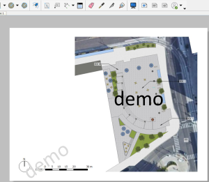
Add labels to the site plan by using the Label tool in the top tool bar.
Point to the different features on the site such as seating area, main intersections, bus stop, stair s focal point, etc.
You can add background to the labels and modify the transparency from the right panel under Shape Style>Fill.
Use the Text tool to add the title for your legend.
Add squares for the different materials located in the site. Use the eyedropper tool to copy material colors from the site and fill the square.
Now we need to add the symbols for the components. Open a new SketchUp file. Draw a rectangle on the ground, then copy paste your components from your site plan’s SketchUp file.
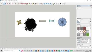
In a top view parallel projection, Zoom in on each component and take screenshots (Shift+Command+3 or Shift+Windows Key+S). Crop the images and save them in a folder named “Symbols”.
You can turn on/off the edges to make the appearance clearer.
Once you took a screenshot foreach component, go back to LayOut. Click on File>insert>go to “Symbols” folder>select your components>Open.
Modify the size for each image and add them to your legend. Hold the Shift key when dragging the blue arrows to resize uniformly.
Add a title: e.g. Site Plan–Waterloo Public Square in the top left.
Add your name, the date, and if applicable, the course code, and your TA’s name to the bottom right.
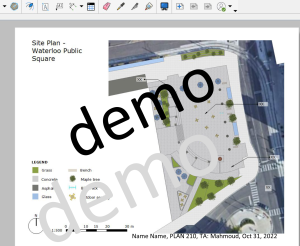
Export your document by going to File>Export>PDF>Options…Set Output Resolution to High and. Rename your file, choose the file destination and and click Save.
Introduction to 3D extrusion
3D extrusion is a fundamental technique that empowers you to bring depth and dimension to your creations. Extrusion involves pulling, pushing, and stretching surfaces to give life to your designs.
It is important to group the different features and objects in your site.
For example, triple click on a 2D drawing of a flight of stairs to highlight all its elements. Right click and Make Group.
Double click the group to edit it.
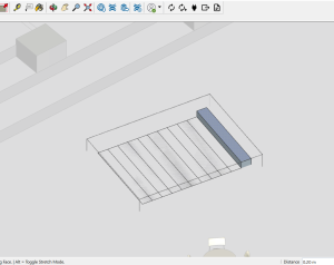
Press “P” on your keyboard to use the Push tool.
Click on the surface you want to extrude and move your cursor in one direction e.g., upwards.
On your keyboard, type a number for your chosen height (you’ll see it indicated in the bottom right corner), then hit Enter.
You can estimate the height of a stair step; they’re usually between 13 cm to 20 cm; double-height stairs or concrete bench/ledges are usually 40 cm in height.
Double click on each step to extrude increments of your chosen number.
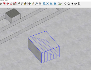
For repetitive objects such as planters, you can choose the Make Component option after right clicking on your object. When you edit one component, changes will be applied to all similar components on the site.