13 Technique: Physical Modelling
michealg1
Introduction
Physical models can be an important tool for public engagement, design, or marketing. They can be used for a variety of contexts and come in many different forms. Before starting a physical model, it is important to understand its purpose and the target audience. For this tutorial, I will be making a simple massing model made of basswood and corkboard. The purpose of my model is to communicate the urban morphology of the site proposal. It will not be extensively detailed nor 100% accurate. I will be using the Bramm Yards site (55 Bramm St., Kitchener) as a study site.
Scale
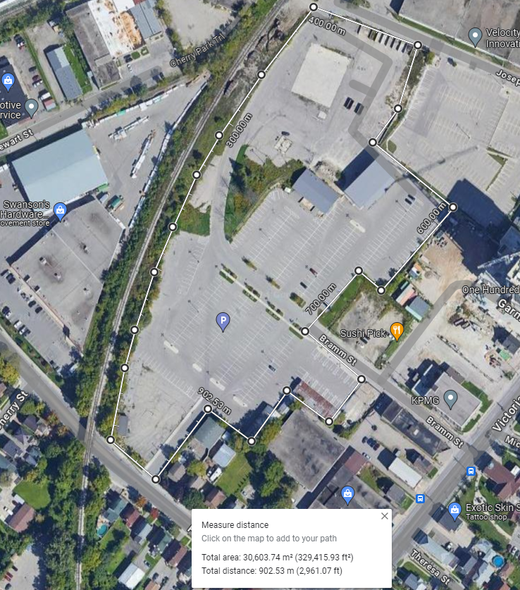
To begin, we must establish a scale relationship between the real-world site and our model. We will start with getting the site dimensions. For reference, this is the rough boundary of the site Bramm Yards site on Google Maps:
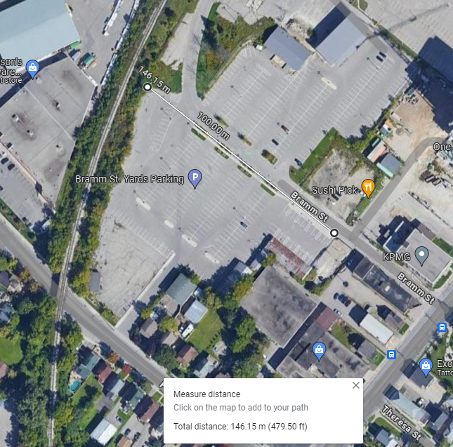
 The width of the Bramm Yards site is roughly 146 meters:
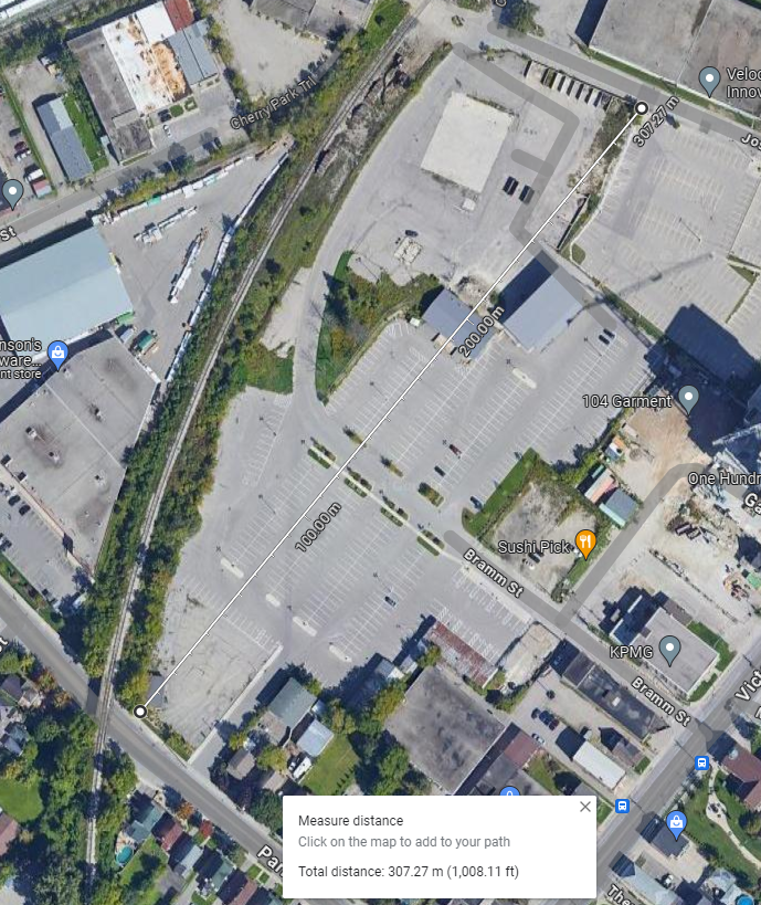
 The length of the site is roughly 307 meters:
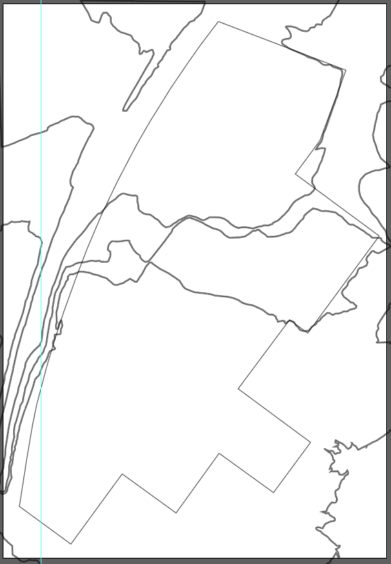
Next, we will need to analyze our site topography. Please refer to previous chapters on how to export contour lines. From our base topography export, we will be tracing each of the lines using a vector-based program such as Adobe Illustrator. Keep in mind that you do not need every topography line, just the ones that are important to your model. Oftentimes, topography is limited to available materials as it is in my case. For example, I had access to 0.5m contour lines and 0.2cm cork material. If I chose to use the 0.5m contour lines with the 0.2cm cork material, I would have a 1:100 scale which would make the model extremely large. Since I cant choose to lower the size of the materials, I do have the option of increasing the size of the contour to bring the scale ratio up. To allow for experimentation, I would advise drawing more topography than needed and deleting unnecessary lines in the future after figuring out an appropriate scale. This is what my topography lines look like after being traced over in Illustrator:
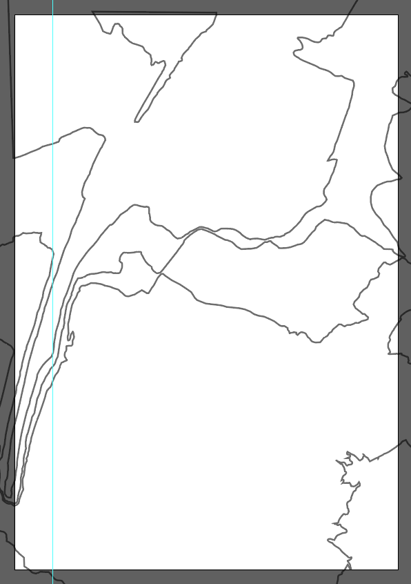
My data source provided me with data on 2m changes in elevation. This means that the difference between each contour line, there is a change in 2 real-world meters. Pay attention to what your own contour lines mean as it is important when establishing your site scale. Our next step would be to take account of our modelling materials. For this demonstration, I will be using corkboard for my landscape and basswood for my site.
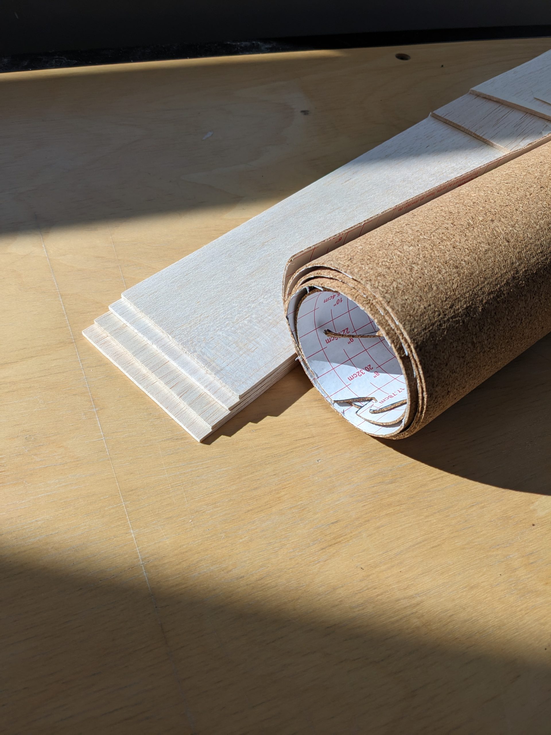
The basswood sheets measure at 0.4cm in width and my corkboard sheets measure at 0.2cm in width. If we relate these widths to that of my elevations, it means that for every 0.1cm on my model, there would be 1m in the real world. This would signal that we are working on a 1:1000 scale. To translate this into the dimensions that we gathered from Google Maps, our site would be 14.6 cm wide and 30.7cm long. At this point, I decided that the theoretical size of my model was appropriate and somewhat accurately reflected the real world.
Digital Scale
After we have found the scale and real-world dimensions of our model, we can resize our topography to match that of the real-world model. Using the dimensions that we gathered from Google Maps, and translating them to model scale (14.6cm, 30.7cm), we can rescale our maps to reflect these exact dimensions. To begin, overlay your site boundaries over your topography:
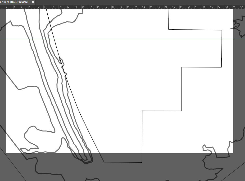
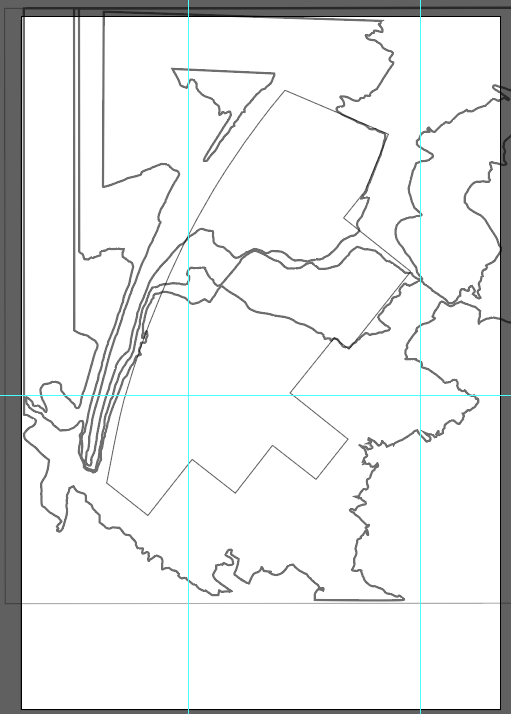
 Next rotate until either the length or the width of the site is parallel to the ruler of Adobe Illustrator. You can select all of your lines using CTRL + A on Windows to avoid misalignment. This is my Illustrator canvas after rotating the lines:
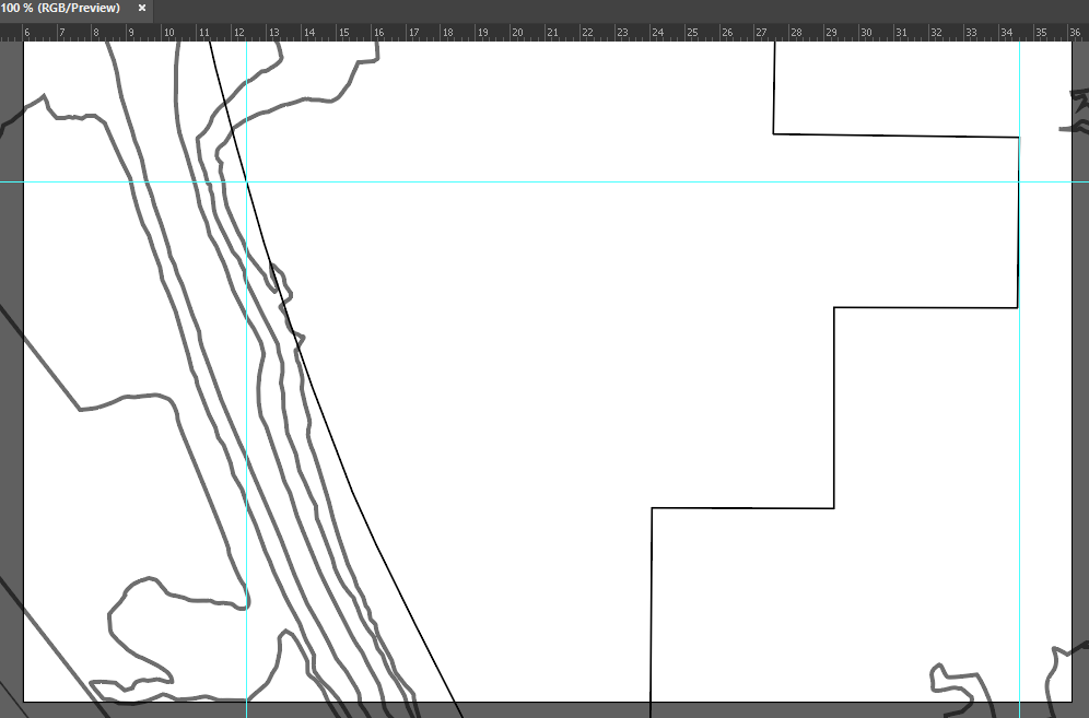
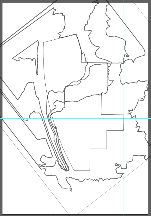
Next, drag guidelines to the intersection points between the length guide line (blue line pictured above) and the site boundaries:
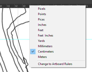
We need to make sure that our ruler is working with centimetre measurements. To check right-click the ruler and select the centimetre option:
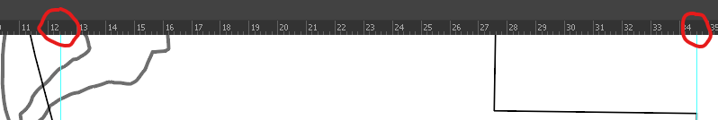
We can see that currently, our site is roughly 22 centimetres by finding the difference between the two endpoints:
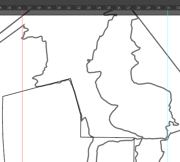
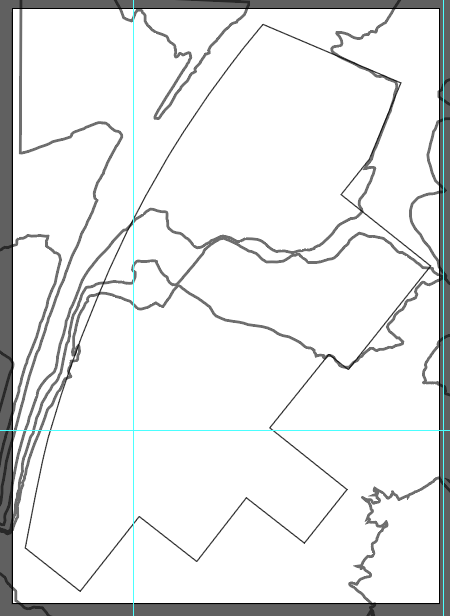
To achieve our desired 14.6-centimetre length, rescale the site until the difference between the two intersections is around 14.6 centimetres. This is what my illustrator canvas looks like now after rescaling:
We can rotate the lines back to their original position:
Our final step would be to resize our canvas size to appropriately frame the site and topography. To do this, use the “Artboard” tool to resize the canvas:
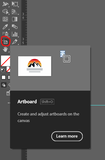
This is what my finished canvas looks like now:
Topography Printing
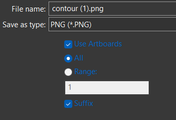
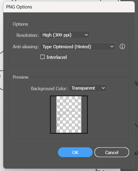
To be able to cut out our topography accurately, we will need a guide to follow. To create a guide, we will be printing the digital topography lines that we created in Illustrator. Export the Illustrator artboard in a PNG file format. Make sure you are using the following export settings:
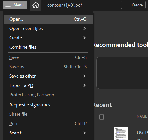
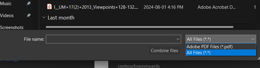
 Next, we need to open our PNG export in Adobe Acrobat. This can be done within Adobe Acrobat using the following directory. Make sure that when looking to open your PNG the “All Files” option is selected as shown below:
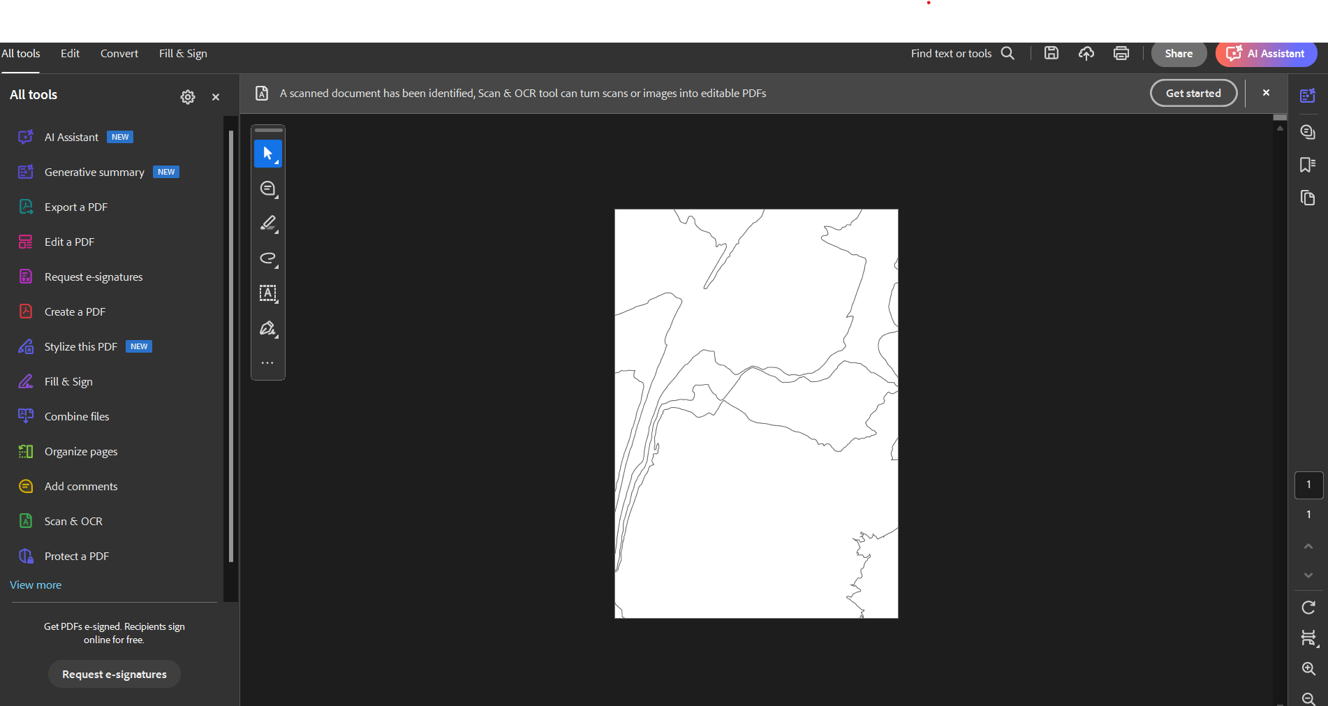
Your Adobe Acrobat should look similar to mine after opening the file:
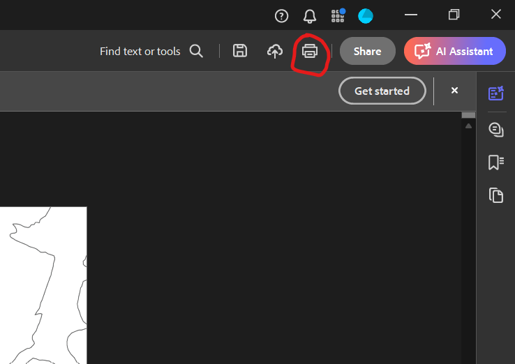
To print, select the “Print this file” option located in the top right:
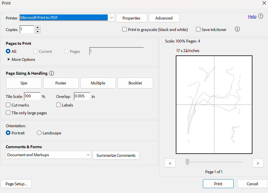
To print the file to its real-world size, we need to use the following printing options. These settings will fragment the PNG into 8.5 x 11in PDF pages to be printer-friendly and remain proportional:
 Save the PDF and print the pages for the next step.
Modelling Topography
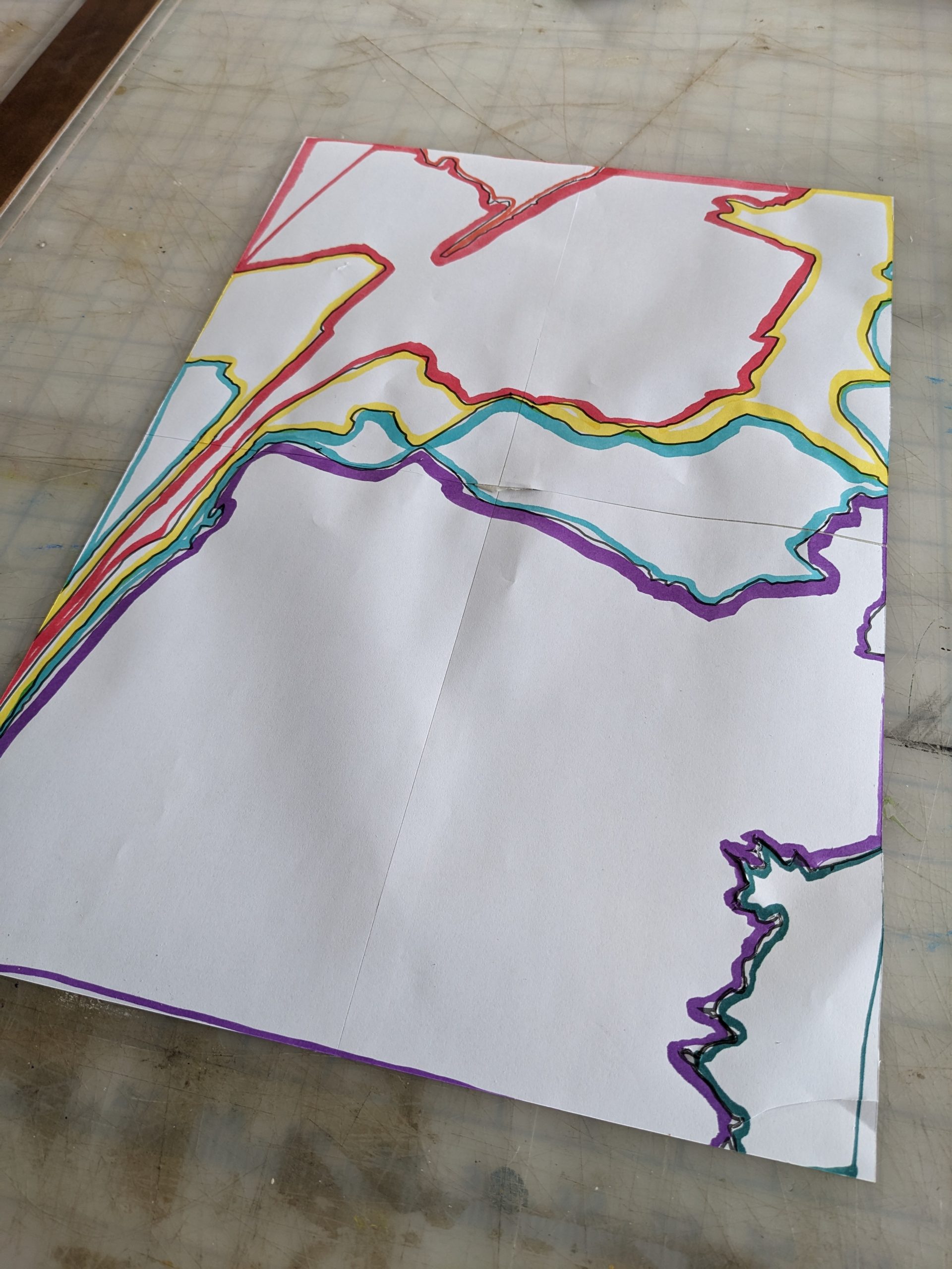
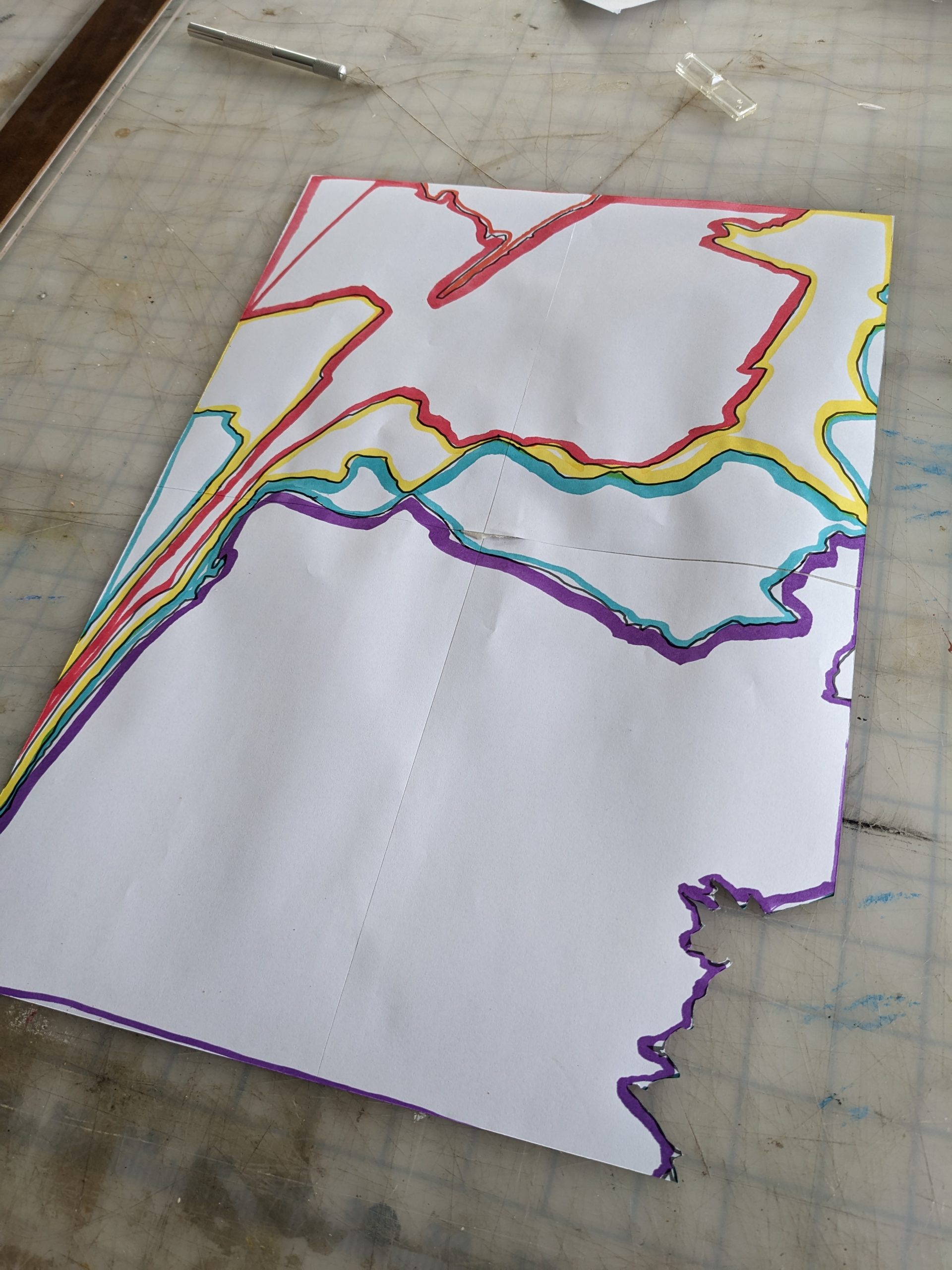
Print your PDF from the previous section. My PDF is four pages which need to be taped together like a jigsaw to be useful. When taping the sheets of paper together, you will notice gaps between the contour lines. These gaps are the printer margins. We will need to fill in these gaps between the contour lines as best we can. After taping the sheets, your contour map should look something like this:
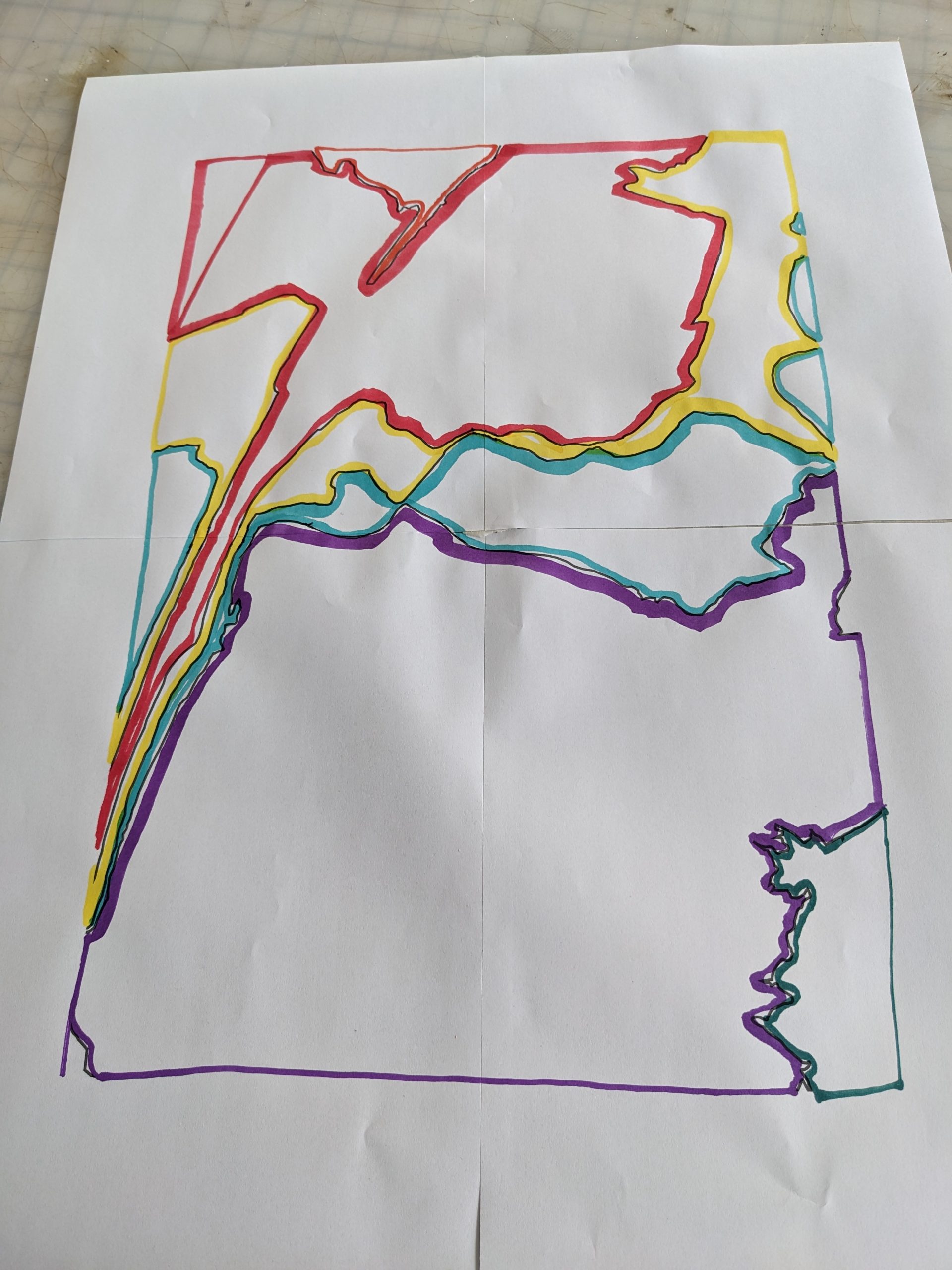 The next step is to out each contour level piece by piece, starting with the lowest level. You will notice that my contour map is colour-coded. I did this to make sure that I was not making any mistakes during this step as I do not wish to waste precious material. I will be starting with the border:
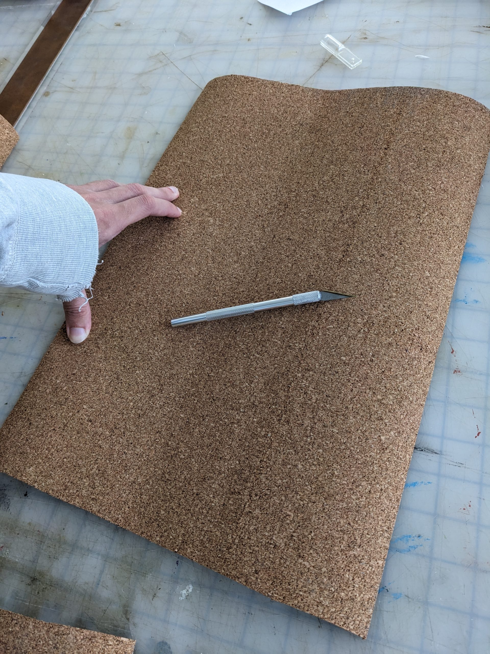
 I will overlay this sheet onto my corkboard material and cut out my first layer of topography using an X-acto knife:
 The next step includes cutting out the lowest topography layer on my contour map. In my case, it will be the small area of dark green in the bottom right corner:
I will then use this full contour map (excluding the small cutout piece) to create the next layer of topography. I repeat this workflow until my topography looks like this:
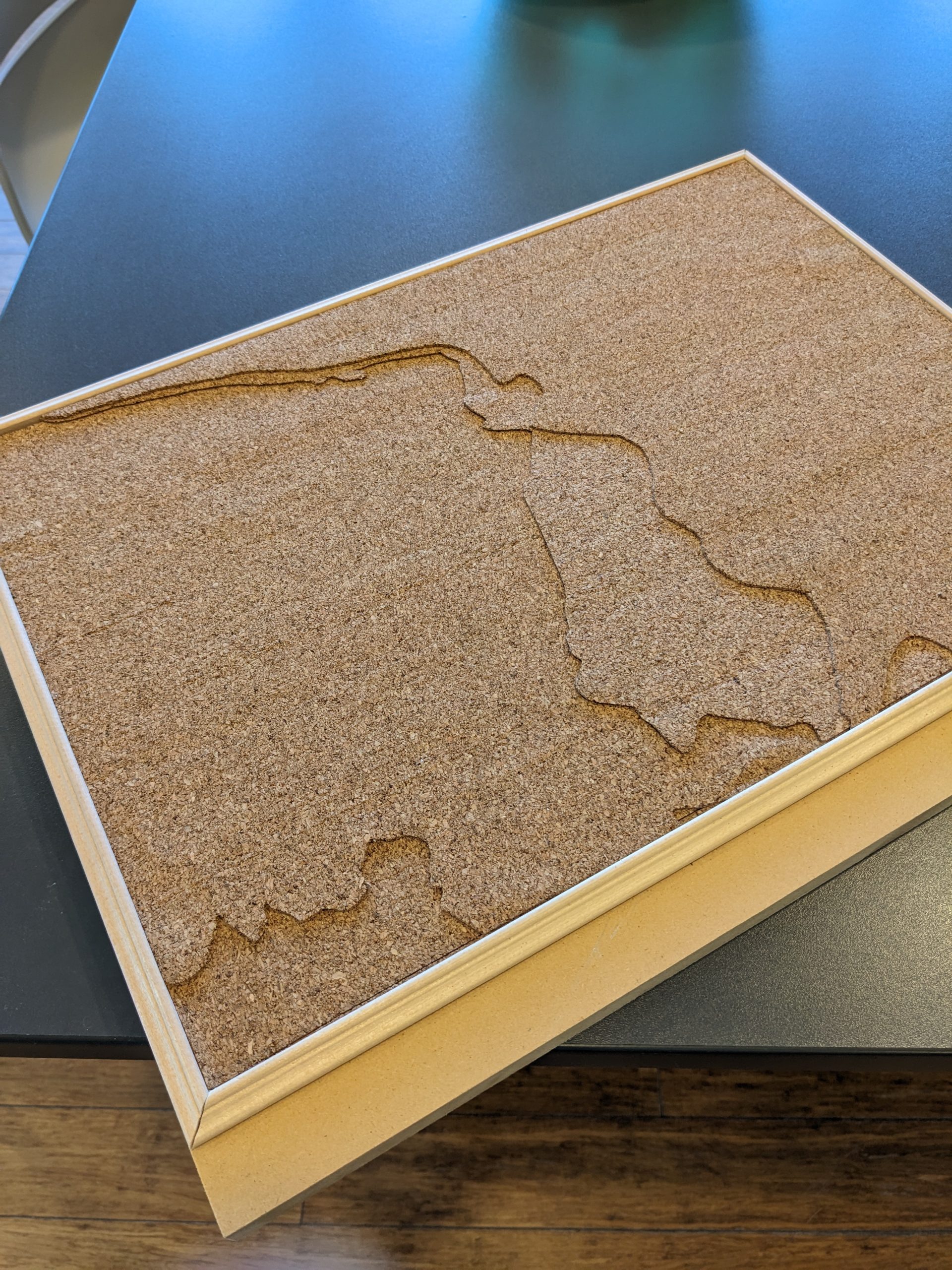
My cork material came with an adhesive layer so I was able to glue each layer together seamlessly. Without the adhesive layer, I would have ideally used gorilla glue or a glue stick. Depending on how malleable your material is, you may be able to use a glue gun. For me, the glue gun would have created extra elevation which is not what I was looking for. You may also notice that I have a nice frame around my topography. I cut out a small scrap of wood and cut frame trims at a 45-degree angle to fit the topography.
Basswood Modeling
Similar to the topography, we need guides to create our massing and site parcel. We will be reusing the exact same Illustrator file made previously, but this time we will be printing just our site parcel. If you have not done so already, trace the site parcel on top of your topography lines in a different layer. Parcel outlines are usually available as a GIS layer file in ArcGIS or are built-in features provided by organizations such as the GRCA mapping tool. I was using the GRCA mapping tool for both my topography and parcel outline. Reusing the same illustrator file but turning off the contour lines, your artboard should look like this:
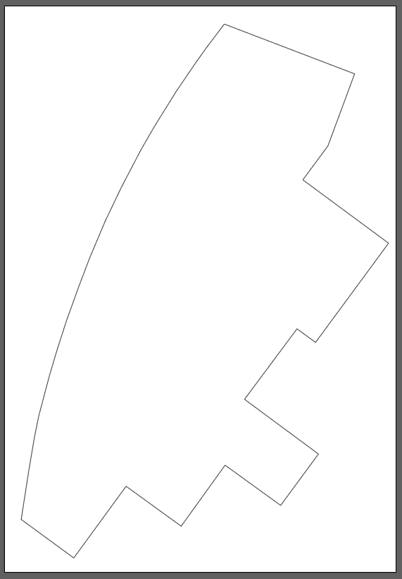
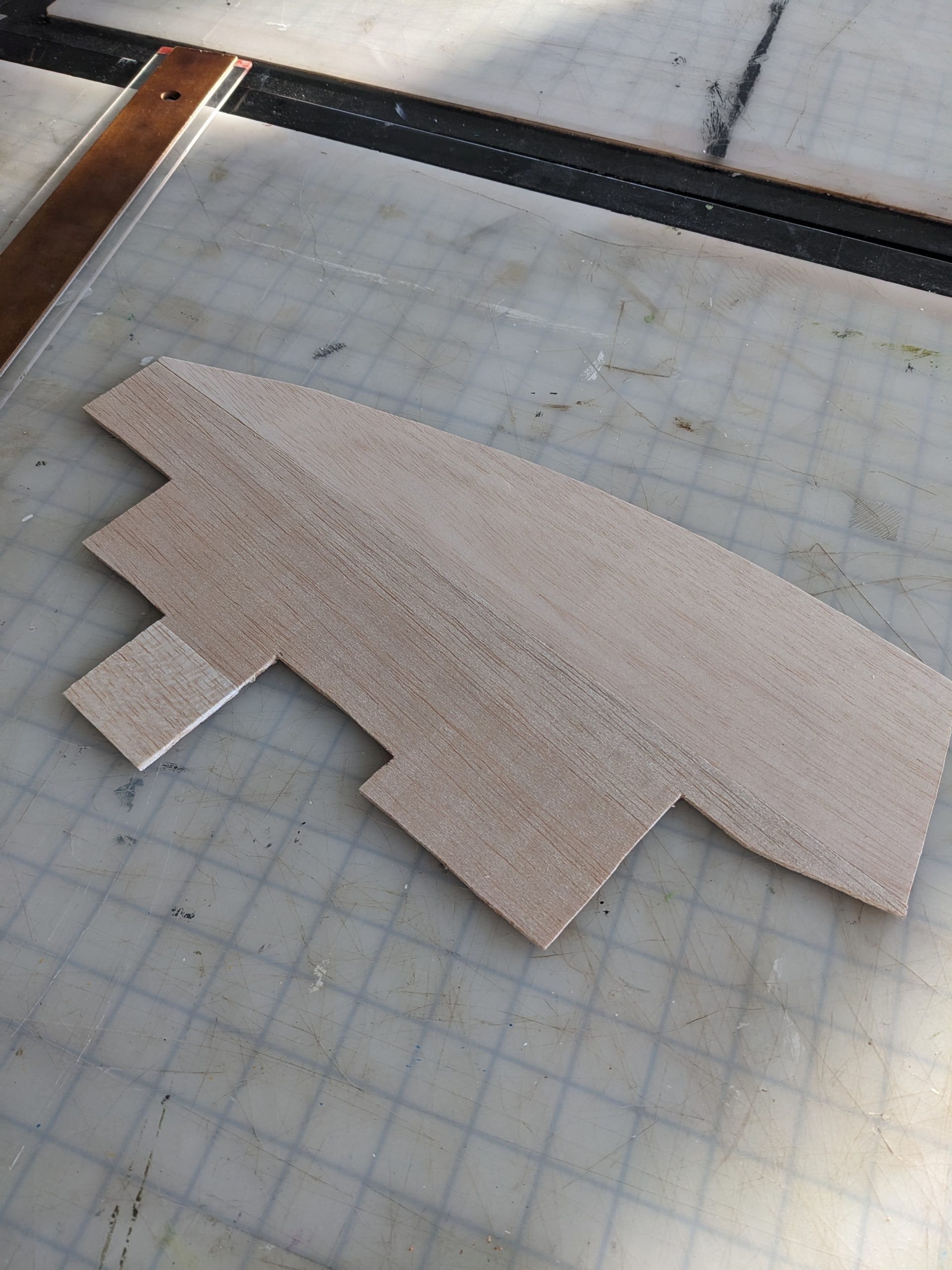
Please follow the same procedures in Adobe Acrobat to print the site to scale. Once printed, tape the sheets of paper together (similar to the topography modelling section) and create a cutout of the site parcel. Use this paper cutout as a guide for cutting the basswood sheet. Your basswood cutout should look similar to this:
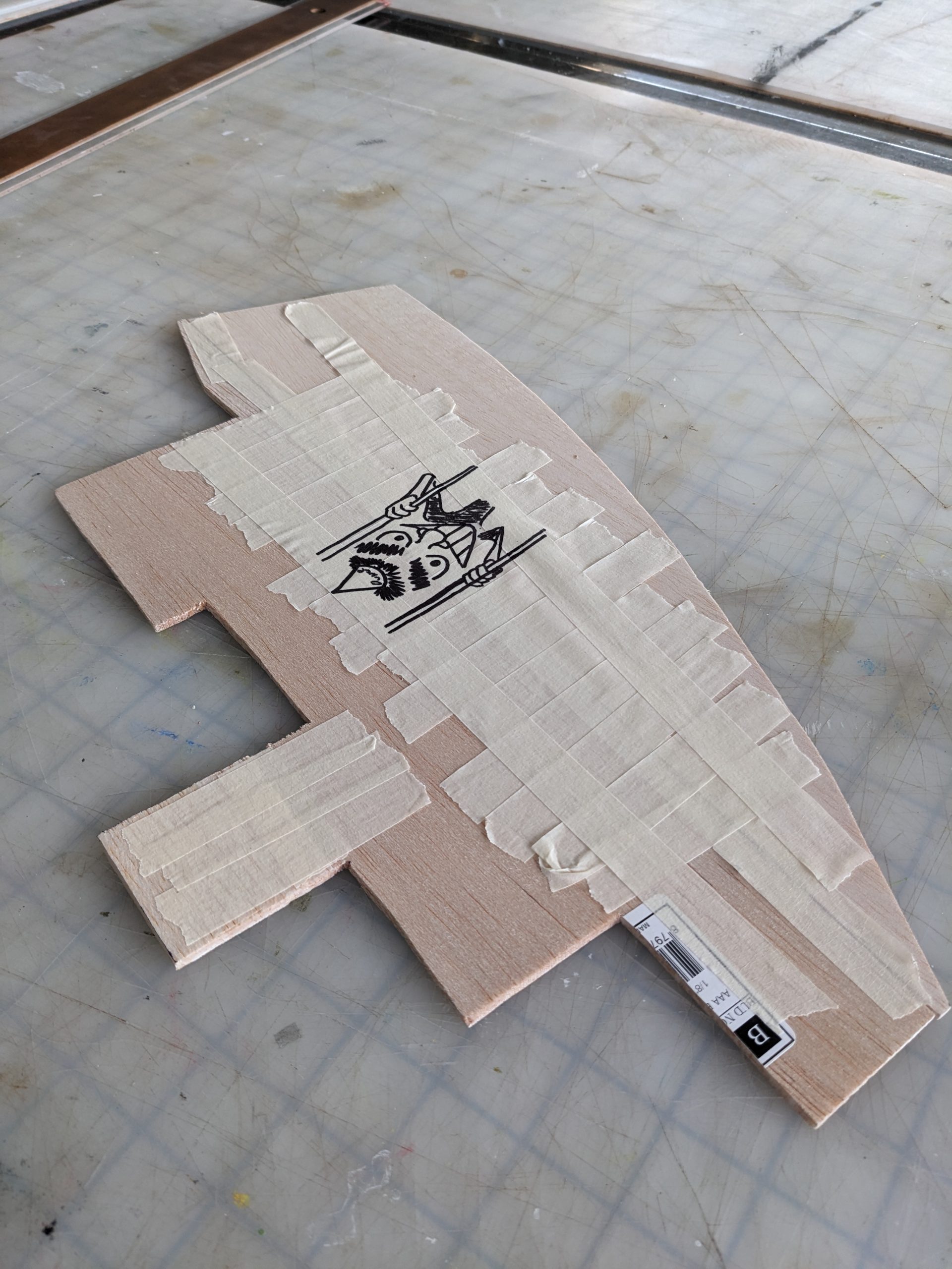
 If your site parcel is too large and does not fit the basswood sheet, you can cut out pieces of the basswood and tape it together using tape. In my case where the basswood was not large enough for a single cutout, I taped the back using masking tape:
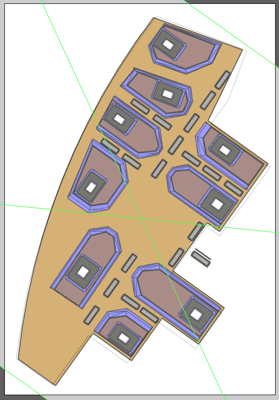
To create the guides for the proposed morphology, I took a top-down screenshot of my conceptual site plan from Sketchup and overlayed it on top of the site boundaries in my Illustrator file. You may already have a more refined and accurate site plan that you could use to overlay but this is what my Illustrator artboard looks like now:
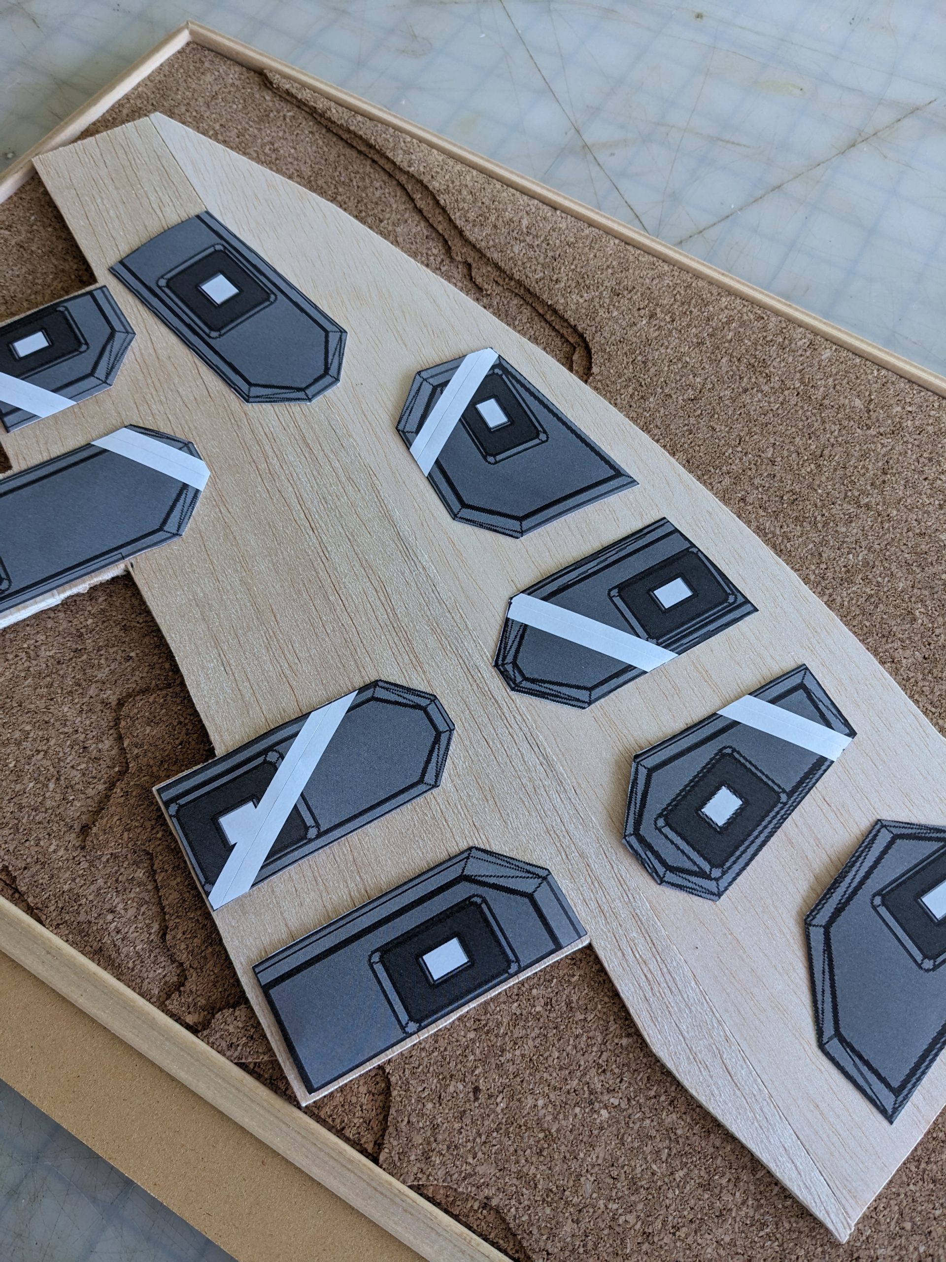
I repeated the steps in printing and creating paper cutouts of my buildings. Similar to the site parcel, I used the paper cutouts as a guide when cutting the basswood. This is what my paper cutouts look like relative to the site parcel:
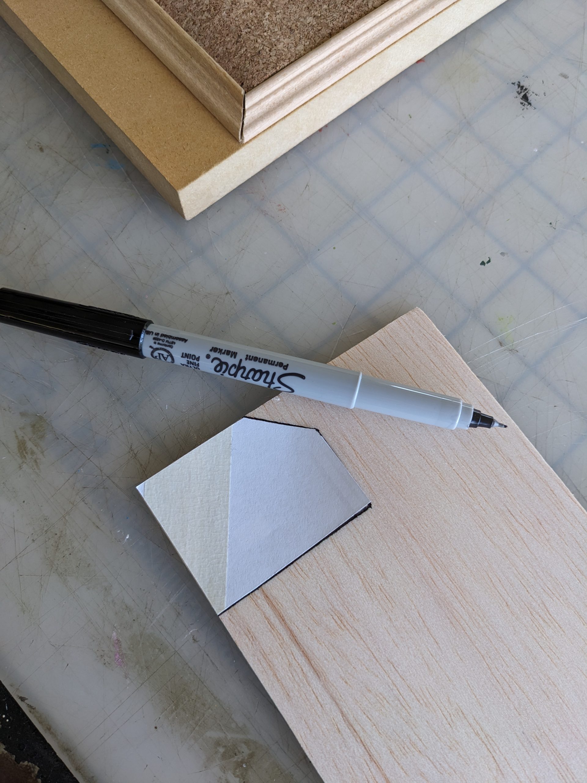
 I used these cutouts to trace outlines in the basswood using a Sharpie:
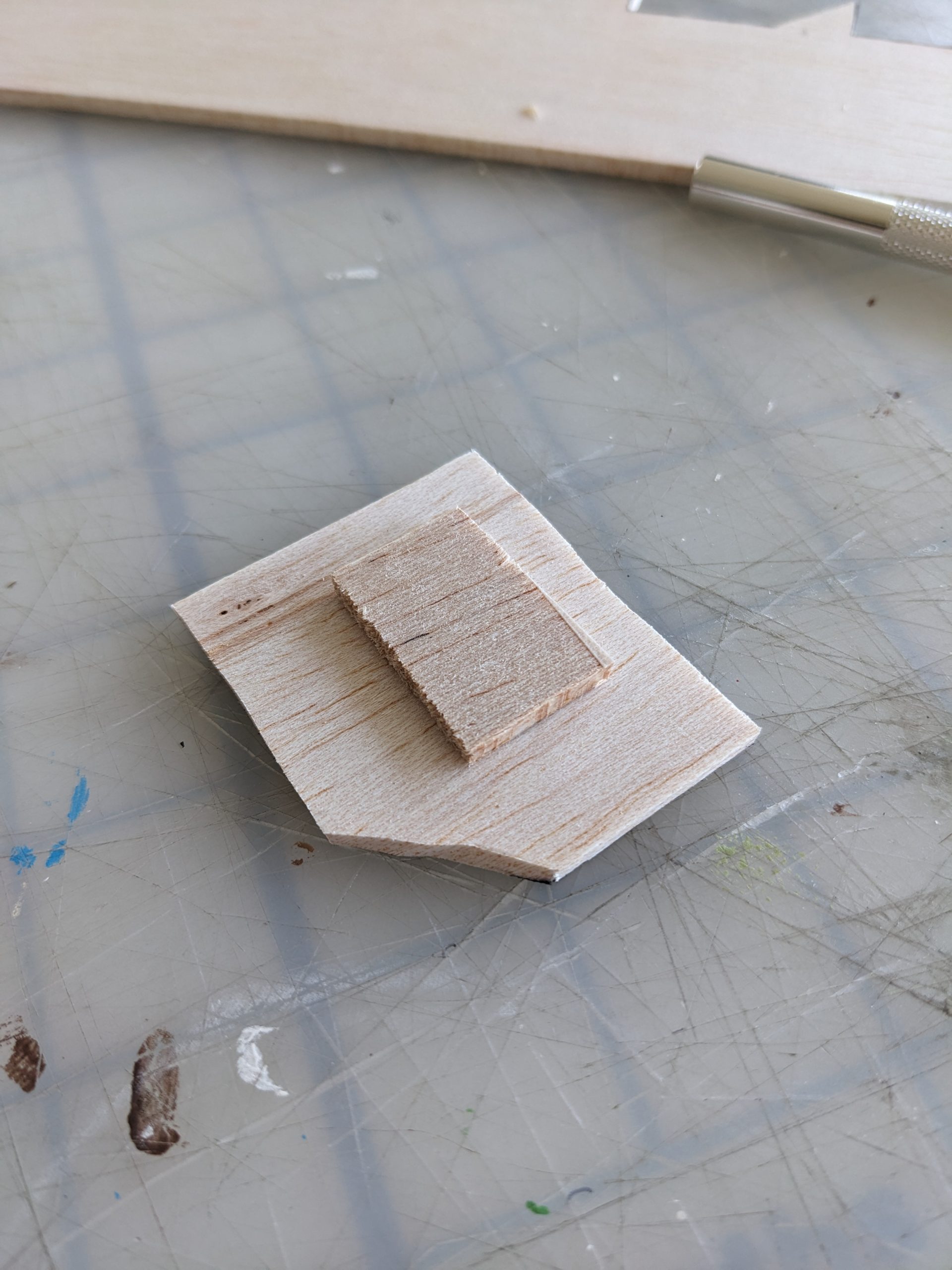
 In my case, my podium is 6 stories (roughly 4 meters per storey). If the width of the basswood is 0.4cm representing 4m in the real world, I would need 6 copies of the podium floorplate. For aesthetic purposes, I will choose to have gaps between my floorplates. I will create these gaps with smaller pieces of basswood that are still 0.4cm in width. This means that I will need 3 copies of the podium template. This process is highly subjective to my own site and things may change depending on your own design. PRO TIP: If you flip the paper guide and trace the inverse, there will be less visible black markings from the sharpie on the final model. This is what my first floor looks like:
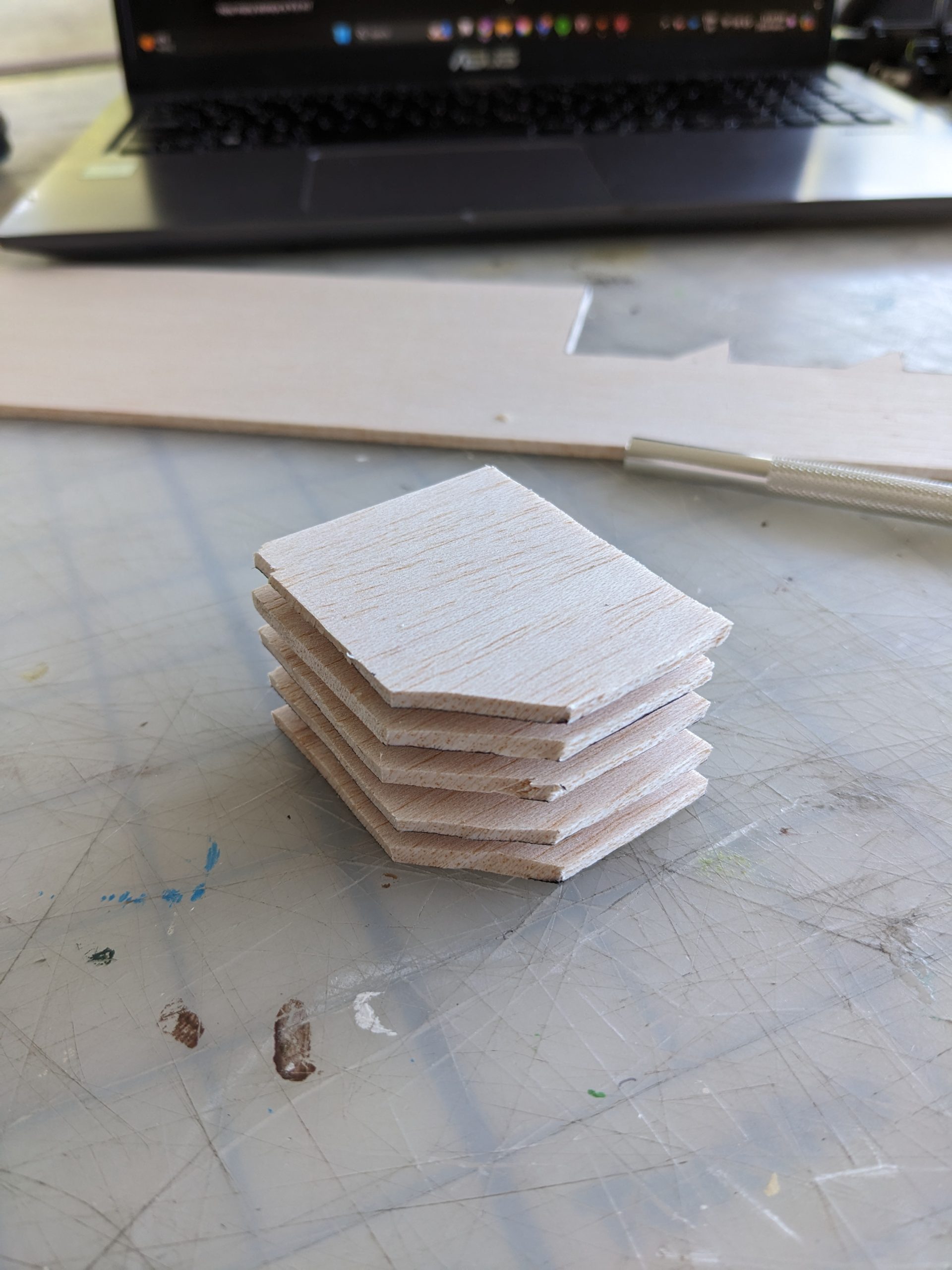
 For the purpose of demonstration, this is what my podium looks like at 2x the massing:
Repeat this process until the remaining towers/podiums/important massing are all present on the site parcel.
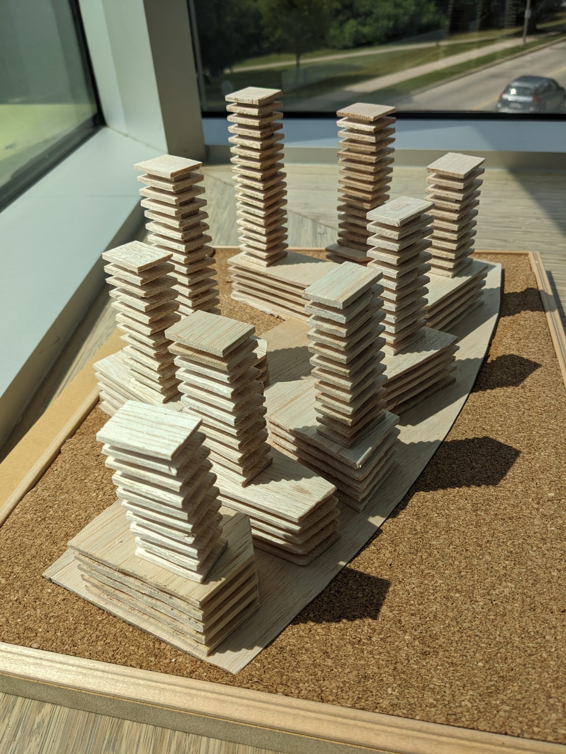
I hope this guide helped you make your first massing model. Physical modelling is a great way to understand the relationship between forms, advertise your proposal, or communicate your ideas or thinking. This guide is very biased towards my process and the materials that I was working with, yours might look completely different and that is okay. There is no wrong or right way to create a physical model, it is all dependent on trial and error with what you are looking for your model to be.
