10 Creating An Assembly
To create an assembly, select the assembly option from the Welcome to SolidWorks Landing Page.
SolidWorks will automatically open a window to import your first part into the assembly. Note: the first 3D model input into the assembly will be fixed and be considered the origin of the assembly.
Choosing the first 3D model will import the part into the new assembly and can be placed anywhere of the users choosing.
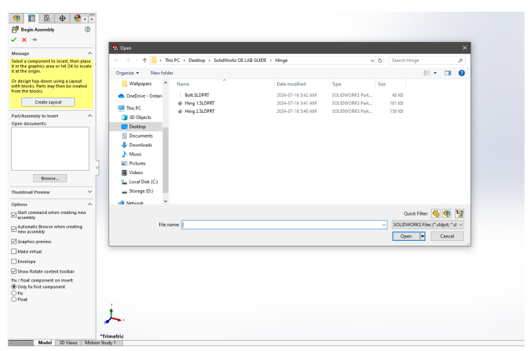
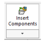
To import more components into an assembly the Insert Components Option Can be clicked in the Assembly Tab.
Now two individual 3D models are placed into the assembly.
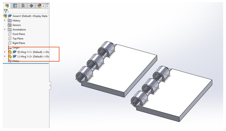
From looking at the Feature Manager Palette it can be noted that the first imported 3D model has the (f) connotation attached while the second model has (-) tagged.
-
- (f) in the assembly means the object is fixed and cannot be moved at all.
- (-) indicated 3D Model is in the float orientation and can be manipulated to move in any direction and orientation.
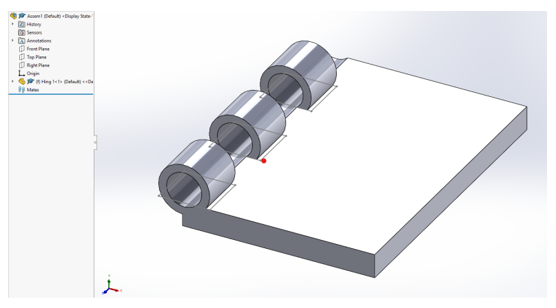
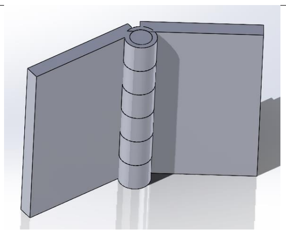
In the example assembly a simple hinge is being assembled. All parts have been brought into the
assembly area. The bolt has been assigned as the fixed part while the two hinges are in the float position.
To truly make a working part in SolidWorks assembly mates have to be used. These mates constrain the movement of parts relative to each other to create a working machine or mechanism.
There are a multitude of mates that are used to constrain two or more parts together. Opening the Mate window from the feature menu will show the available mates that can be used.
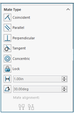
▪ Coincident – The two selected parts are in contact. Vertices, edges, faces can be selected while using the coincident mate.
▪ Parallel – The two selected parts will always be parallel to each other regardless of orientation and location. Faces and edges can be selected for the parallel mate.
▪ Perpendicular – Two selected parts are perpendicular to each other (90 Degree orientation). Edges and faces can be selected for the perpendicular mate.
▪ Tangent – Ensures that a cylindrical Part will always be coincident with a face or edge.
▪ Concentric – Concentric mate ensures that two circular parts will have the origin of their circle lined up center to center.
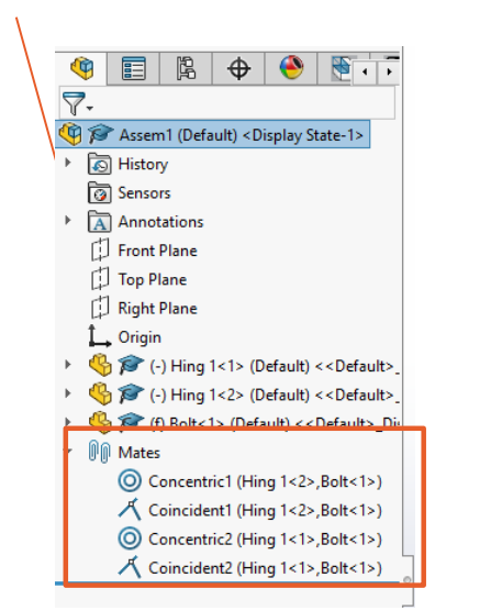
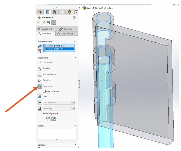
First the concentric mate will be used for both hinge plates to line them up with the fixed bolt. Opening the mate menu the concentric edge of hinge one is selected alongside the long edge of the bolt.
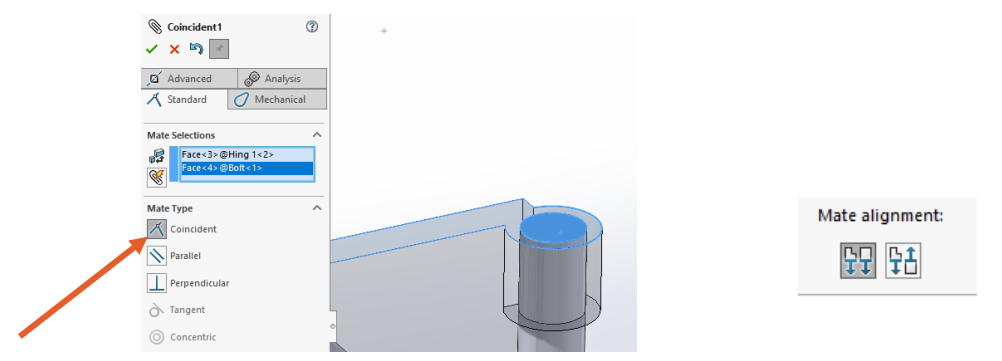
Next the Coincident mate is used to line up the edges of the two parts to each other. The direction of mates can also be changed from the Mate Feature Menu using the Mate Alignment Feature.
Similar Process is used for Hinge #2 with concentric and coincident mates.
With the mates applied both hinge doors can be freely moved by clicking and dragging them into the orientation desired, SolidWorks will automatically handle mates and won’t allow a part to be moved that is not within the limitation assigned by the constraining mates.
All mates assigned in the assembly are listed in the Feature Manager Palette. Each Mate can be individually adjusted if needed. Mates can also be suppressed to not apply to an assembly if desired, this is useful for large assemblies which may have hundreds of mates present.