12.1. Concepts: Transmitting rotational motion through gears
Introduction
Gears are wheels with teeth on their periphery and are used to transfer motion and power between machine components. The teeth prevent the slippage that occurs when two simple disks transmit motion from one another through friction. Two gears that mesh with each other can be classified as drivers and driven.
The driver gear will transmit motion to the driven one. If their diameters are different, while motion is transmitted, there will be a change in the rotational speed from one gear to another. Gears are used to either decrease or increase the rotational speed, depending on the application in which they are used.
Concepts
If we consider two disks, one of diameter D rotating at a speed of N rpm and one of diameter d, rotating at n rpm, then we can say that the point of contact between them will rotate at the same tangential speed, [latex]\boldsymbol v[/latex].
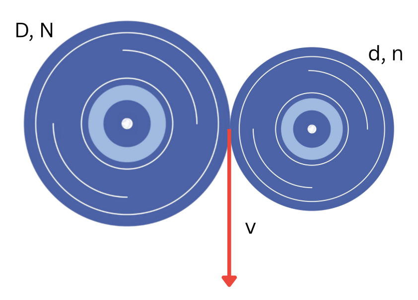
Expressing the tangential speed from both the disks, we get:
[latex]\omega_1 r_1 = \omega_2 r_2[/latex] (1)
If we substitute both angular velocities using the conversion of units below:
[latex]\omega = N \times {\large \frac{2\pi}{60}}[/latex] (2)
and the radii by the respective diameters, formula (1) becomes:
[latex]N \times D = n \times d[/latex] (3)
In the case of gears meshing with each other, the contact point is positioned on the reference diameter (reference circle) – see picture below.

The module is a characteristic of gears, and it is equal for gears that mesh with each other. The module is defined as:
[latex]m = {\large \frac{\text{pitch}}{\pi}}[/latex] (4)
The reference diameter is equal to the circumference/ [latex]\pi[/latex], which means:
[latex]D = {\large \frac{\text{pitch} \times T}{\pi}} = m \times T[/latex] (5)
If we substitute formula (5) into formula (3), we get the equation of gears:
[latex]N \times T = n \times t[/latex] (6)
where:
[latex]N[/latex] - represents the number of revolutions per minute for the driver gear;
[latex]T[/latex] - represents the number of teeth for the driver gear;
[latex]n[/latex] - represents the number of revolutions per minute for the driven gear;
[latex]t[/latex] - represents the number of teeth for the driven gear.
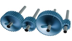
Gear trains. When there are more than two gears involved in the transmission of motion, they are called gear trains.
Gear trains can be simple gear trains (Figure 12.3 a) or compound gear trains (Figure 12.3 b).
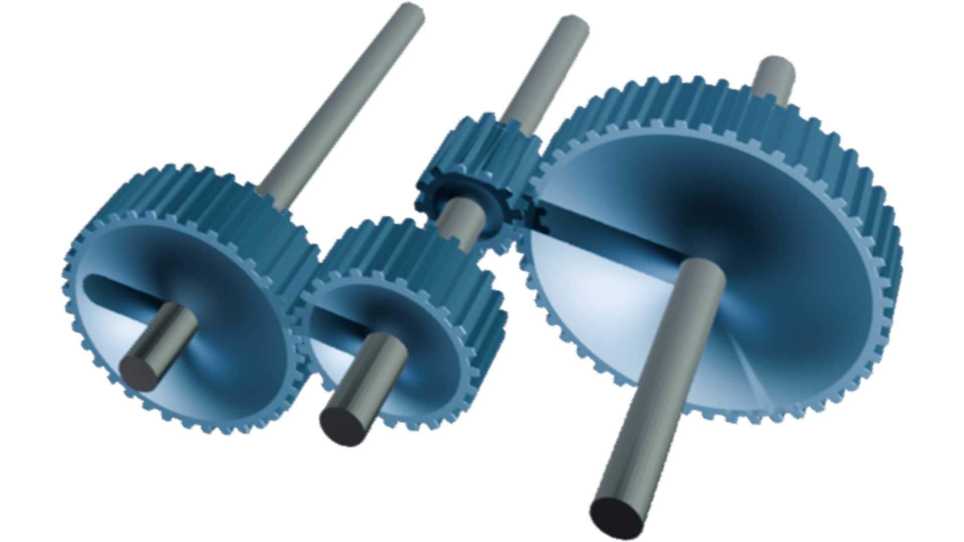
When the number of gears is even, the first and the last gear will rotate in the same direction; when the number of gears is odd, the first and the last gear will rotate in opposite directions.
The general formula for the gear trains can be adapted from the general gear equation (formula 6), as follows
[latex]N \times T_1 \times T_2 \times T_3 \dots = n \times t_1 \times t_2 \times t_3 \dots \text{ (7)}[/latex]
where:
[latex]N[/latex] - represents the number of revolutions per minute for the first driver gear;
[latex]T_1, T_2, T_3, \dots[/latex] - represents the number of teeth for the driver gears;
[latex]n[/latex] - represents the number of revolutions per minute for the last driven gear;
[latex]t_1, t_2, t_3, \dots[/latex] - represents the number of teeth for the driven gears.
Image Attributions
- Figure 12.1 adapted from:
- Illustration of gear doodle icon by rawpixel.com courtesy of Freepik
- Figure 12.2 adapted from:
- Illustration of a cogwheel by rawpixel.com courtesy of Freepik
- Figure 12.3 adapted from:
- Gears V2.0 by Helindu courtesy of Sketchfab, CC-BY 4.0
