Chapter 3. Vector addition
Learning Objectives
By the end of this chapter, you will be able to:
- Add multiple vectors graphically.
- Solve questions involving algebraic addition of multiple vectors.
Introduction
There are many situations arising in daily life or encountered in the sciences where vector addition is used to solve a problem. This is why adding vectors is a fundamental concept in physics and engineering, and one often seen in various real-life scenarios.
For instance, if a boat’s engine gives a velocity to the boat directed east and the water current flows with a velocity directed south, then we would need to add the two velocity vectors to find the real magnitude and direction of the resultant velocity of the boat.
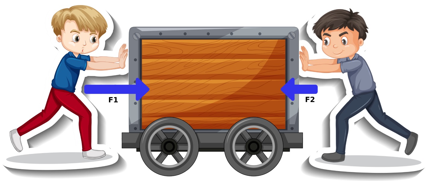
Another example would be an object subjected to two or more forces directed in different directions (see image below). To find the net force acting on the object and the direction the object is moving, we would need to add all those force vectors and find a resultant.
3.1 Concepts
Adding vectors can be done graphically or algebraically.
3.1.1 Graphical methods
Graphical methods are based on measuring and drawing. The equipment needed includes a ruler, a protractor and squared paper.
We will present two graphical methods: the polygon method and the parallelogram method.
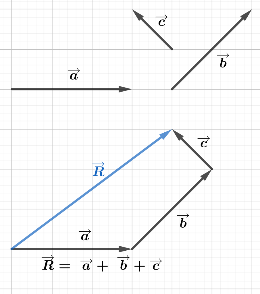
3.1.2 The polygon method
Adding two vectors in the polygon method involves the following steps:
- Choose a convenient scale. Measure and draw the first vector.
- Place the second vector with the tail to the tip of the first one.
- Continue to measure and draw the remaining vectors, each with the tail to the tip of the previous vector.
- The resultant will be the vector that connects the tail of the first vector to the tip of the last vector.
Example
Given vectors a, b, and c below, find the resultant by adding the vectors using a polygon method.
3.1.3 The parallelogram method
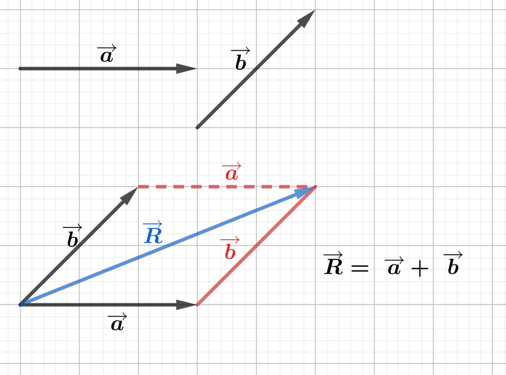
To add two vectors using the parallelogram method follow these steps:
- Choose a convenient scale and draw the vectors with the tails in the same point.
- Draw parallel lines to both vectors to create a parallelogram.
- Connect the common tail of the vectors to the opposite end of the parallelogram (the diagonal). This will be the resultant (the sum of the two vectors).
Example
Given a and b below, find the resultant by adding the vectors using a parallelogram method.
3.1.4 The algebraic method
Adding vectors by using the algebraic method involves using the components of all vectors to be added. This is a precise method compared to the graphical method, since the latter relies on the precision of the instruments used for measuring and drawing, the thickness of the pencils, human measuring and drawing skills, etc.
To add vectors using the algebraic method, follow these steps:
- Sketch the vectors on a Cartesian plane.
- Make a table of the vectors and their components so that the x- and y-components can be added separately to find Rx and Ry (representing the x and y components of the resultant).
- Determine the quadrant in which the resultant lies.
- Calculate the magnitude of the resultant by using the Pythagorean theorem.
- Calculate the reference angle using the trigonometric function tangent.
- Calculate the angle in standard position by using the formula relating the reference angle to the standard position angle (according to the respective quadrant); see the equations in Chapter 2.
3.2 Solved example
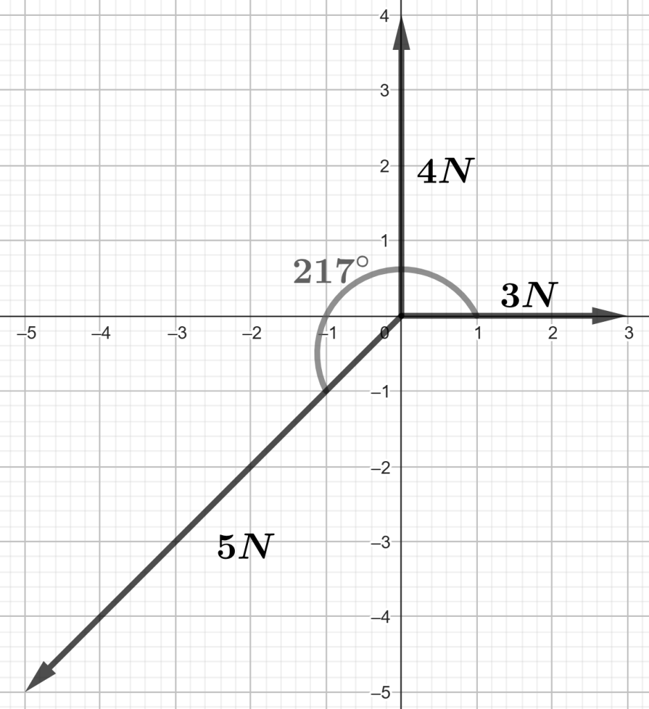
Three forces act on a point: 3 N at 0°, 4 N at 90°, and 5 N at 217°. What is the net force? Round off intermediate answers to whole numbers.
|
[latex]x_{components}[/latex]
|
[latex]y_{components}[/latex] | |
|---|---|---|
| [latex]\overrightarrow{F1}[/latex] | 3 | 0 |
| [latex]\overrightarrow{F2}[/latex] | 0 | 4 |
| [latex]\overrightarrow{F3}[/latex] | [latex]5 * \cos(217°) = -4[/latex] | [latex]5 * \sin(217°) = -3[/latex] |
| [latex]\overrightarrow{R}[/latex] | -1 | 1 |
Step 1. Calculate both x and y components of all vectors that are to be added, and organize the information in a table (as shown above).
Step 2. Add all x components and then all corresponding y components, and write the results in the last row. The results represent the x component and the y component of the resultant, R.
Step 3. Calculate the magnitude of the resultant by using the Pythagorean theorem:
[latex]R=\sqrt{x^2+y^2}=\sqrt{2}=1.41N[/latex]
Step 4. Decide what quadrant the resultant lies into, by analyzing the signs of the components. Since the x component is negative and the y component is positive, the resultant will be positioned in the second quadrant.
Step 5. Calculate the reference angle related to the resultant by using the inverse tangent:
[latex]\alpha=\tan^{-1}(\frac{\left|y\right|}{\left|x\right|})=\tan^{-1}(\frac{1}{1})=45°[/latex]
Step 6. Calculate the angle in standard position related to the resultant by using the corresponding formula for the quadrant of the resultant.
Recall:
Quadrant 1: [latex]\theta=\alpha[/latex]
Quadrant 2: [latex]\theta=180°-\alpha[/latex]
Quadrant 3: [latex]\theta=180°+\alpha[/latex]
Quadrant 4: [latex]\theta=360°-\alpha[/latex]
Quadrant 2: [latex]\theta=180°-\alpha =180°-45°=135°[/latex]
Answer: [latex]R=1.41N,\theta=135°[/latex]
Try it!
- A resultant displacement with both x and y components negative will be positioned in
what quadrant? - Suppose a velocity vector is positioned 67° south of east. What is the quadrant for the vector?
- a) When adding the x components of all vectors involved in a vector addition question, what do we find?
b) When adding the y components of all vectors involved in a vector addition question, what do we find?
Practice
- A robotic arm is programmed to move in three successive displacements in a factory. The first displacement vector, A, has a magnitude of 2.5 metres and is directed at an angle of 30 degrees north of east. The second displacement vector, B, has a magnitude of 3.0 metres and is directed vertically upward. The third displacement vector, C, has a magnitude of 4.0 metres and is directed at an angle of 50 degrees south of west. Calculate the magnitude and direction of the resultant displacement vector that represents the overall motion of the robotic arm in the factory.
[latex]1.25 m, 109°[/latex]
- A hiker follows the route indicated in the figure below. Find:
- The magnitude of the hiker’s displacement.
- The direction of the resultant displacement.
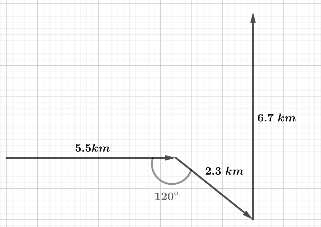
Figure 3.5 Hiking trail vectorial representation. [latex]8.1 km, 35°[/latex] - Three forces are exerted on a crate placed on a horizontal floor. They are directed as shown in the figure. If the forces have magnitudes F1= 5.00 N, F2= 18.0 N, and F3= 12.0 N, what is the the net force perpendicular to the floor?
NOTE: The net force is the vector sum of all external forces acting on an object:
[latex]\overrightarrow{Fnet}=\sum\overrightarrow{F}[/latex]
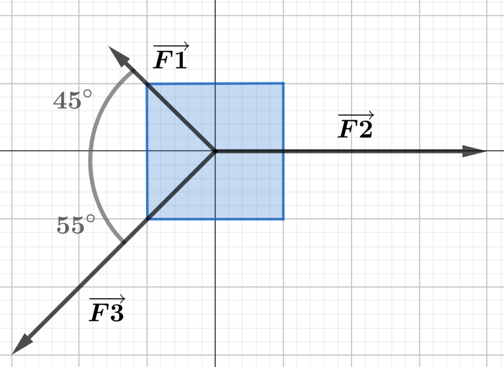
Figure 3.6 Forces on a crate vectorial representation. [latex]12.2N,211.1°[/latex]
Challenge Questions
Image Attributions
-
- Figure 3.1 adapted from:
- Wooden Cart on White Background designed by Freepik.
- Boy pushing something by Freepik (left-side) designed by Freepik.
- Boy pushing something by Freepik (right-side) designed by Freepik.
- Figure 3.2 – 3.6: Created with Geogebra and licensed under CC-BY-SA-NC 3.0
- Figure 3.1 adapted from:

