Exotic Interferometry
Introduction
Michelson-Morley Interferometer
Interferometers are powerful tools for examining our universe. They were used to dispel the concept of ‘aether’, which was a substance believed to fill empty space. More recently, interferometers have been used to detect gravitational waves by the LIGO experiment, and much more.
Interferometers are used to measure change. A schematic of a Michelson-Morley interferometer (which hopefully you recognize from some earlier physics courses) is shown in Figure 1. The light enters and is split into two perpendicular paths. Each path ends in a mirror, with the reflected beam overlapping the incoming beam as much as possible. The output of
the interferometer will show evidence of the constructive and destructive interference due to the overlapped electromagnetic waves.
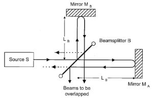
The output of the interferometer will not change unless something changes one arm if the interferometer relative to the other. For example, if the length of one arm was changed relative to the other, the interference pattern would sinusoidally cycle through constructive and destructive interference. The number of cycles and the change in the length if the arm can be used to determine the wavelength of the light according to
 ,
,
where  is the distance moved,
  is the number of cycles, and
  is the wavelength of the light source.
It just so happens that there are many types of exotic interferometers that offer greater functionality and/or precision compared to the OG Michelson-Morley interferometer.
Quadrature Interferometry
In the quadrature interferometer, as shown in Figure 2, a dielectric metal beam splitter is added before the MM interferometer. It’s true that half of the input light is then lost, but all of the light that enters the interferometer will be used to generate the constructive and destructive interference within the interferometer and exit from one of the two 50/50s. The output should be complementary, in that when one out shows the constructive interference (i.e be very bright), the other will show deconstructive (i.e. be very dim). COMMENT about both outputs being measured and why that results in a locus and how that makes it insensitive to displacement.

The Sagnac Interferometer
The previous interferometers relied on the beams of light perfectly overlapping inside the interferometer, but that isn’t actually necessary for an interferometer to work. The only condition we need is that the output beams overlap so that the user can observe the constructive and destructive interference. The Sagnac interferometer, shown schematically in Figure 3, relies on polarization, which is the direction of oscillation of the electric field of the laser light. The incoming beam is at 45 to the vertical. The beam cube splits the incoming light into horizontal and vertical polarizations. The two beams travel through the square-shaped path in opposite directions. The distance they travel is almost identical (unlike the MM where the two arms may be different length). In theory, this aspect of the Sagnac interferometer will give optimally distinct fringes in the output such that the output beam appears to blink on and off instead of having multiple fringes.

Because the two beams of the Sagnac interferometer don’t have to overlap, we can spatially separate them and see what happens to the output when we change the path of one beam. For example, one could insert an optically transparent chamber filled with some gas as in Figure 3, and see how the output changed as a function of gas pressure.
The phase change is given by
(1) 
where  is the wavelength of the light in vacuum,
  is the change in index of refraction (really
  since
since  in vacuum), and
  is the length of the column where the gas pressure is changing. The phase shift is actually double this value because of the two-way passage of the light. Each fringe count
  between vacuum and atmosphere is given by
(2) 