Faraday Rotation
Experimental Apparatus
The apparatus (minus the electronics) is shown in Figure 4. The laser enters the first polarizer to select just one component of polarization. The now-completely-linear light travels through the sample in the solenoid. The change in polarization is detected with the second polarization filter before the detector.

Figure 4: Schematic of the Faraday rotation apparatus.
The instruments are shown in Figure 5 and the circuit diagram in Figure 6.
3.1 Polarizers
There exist a wide variety of optical polarizers for various applications. Some are made by stretching polymers and filling channels with charged particles, some take advantage of changes in index of refraction and Brewster’s angle, but they all basically work by making evenly-spaced striations such that electromagnetic radiation that oscillates parallel to striations can pass through while oscillations in other directions are either reflected or absorbed. Two polarizers held perpendicularly to each other will, in theory, allow no light to pass through. Practically, polarizers are not perfect and some small amount of light can penetrate them both.
3.2 Diode Laser
The light source for this experiment is an polarized diode laser operating at about 1 mW (part number VLM-650-03 LPT) . The laser power is low enough that safety goggles are not necessary. Still, please do not point the laser at your face or put your face on the same plane as the laser beam. The laser requires up to 5 V from the power supply it is connected to, though you will probably operate around 2.5 V. No need to adjust the current.

Figure 5: Instrumentation used in the Faraday Rotation experiment. Instructions on how to connect the instruments is in the procedure section.
3.3 Solenoid
A solenoid is an incredibly simple and useful arrangement of wire – it’s just a cylinder. You probably took some intro EM course and learned that the magnetic field of a solenoid points along the axis of the cylinder and has a value of
(7) 
where  is the magnetic constant,
  is the number of turns of wire,
  is the current in the wire, and
  is the length of the solenoid. Once the solenoid is constructed, the user really only has control over the current, so solenoids are often described just by their magnetic field/current ratio (G/A), or (T/A) if you prefer SI units (hint: you do). The solenoid used is this experiment generates 20.0 mT/A.
3.4 Photodiode
The photodiode generates current, and so the measured voltage depends on the load resistance, which in this case is the internal resistance of the measurements devices. You will measure the internal resistance of the oscilloscope and lock-in amplifier directly. These values are then used to determine the current that results from the laser light hitting the photodiode.
The photodiode used in this experiment is a battery-operated unit from Thorlabs. The output is 0-5V. If the detector is ever outputting more than 4.5 V, then it is oversaturated and changes in the signal will not be measured accurately. The photodiode has a relatively small active area, so a relatively large lens is used to focus the beam.
3.5 Lock-In Amplifier
Simply turning the solenoid on, measuring the photodiode current, then turning the solenoid off and measuring again is insufficient for a precise measurement of small Verdet constants. The noise in the signal will have a much larger amplitude than that caused by the change in polarization. The solution is to modulate the magnetic field and use a lock-in amplifier. The unit used in this experiment is the SR510, as in Figure 7. This unit can measure signals with amplitudes on the order of nanovolts even in the presence of noise at other frequencies with amplitudes many orders of magnitude larger.

Figure 6: Circuit diagram for the (a) DC and (b) AC Faraday Rotation measurements.
3.6 Samples
The glass rod used in the first series of measurements is a type of dense flint glass called SF57. This type of glass contains lead oxide, resulting in it having a relatively large Verdet constant of 20.1 rad/(T*m). The rod is 10.0 cm long. The faces of the rod are polished so that they are optically transparent. DO NOT TOUCH THE FACES OF THE GLASS ROD. Your fingerprints are not optically transparent.
The distilled water sample is held in a glass cylinder that fits nicely into the solenoid. Again, DO NOT TOUCH THE FACES OF THE CYLINDER. The cylinder has already been filled with distilled water, which has a Verdet constant of 3.35 rad/(T·m) – about six times smaller than that of the dense flint glass. The length of the water column is 21.0 cm.
There are some specifically designed crystals such as terbium gallium garnet (TGG) that have Verdet constants on the order of 100 rad/(T·m), making them useful in constructing a Faraday Isolator.
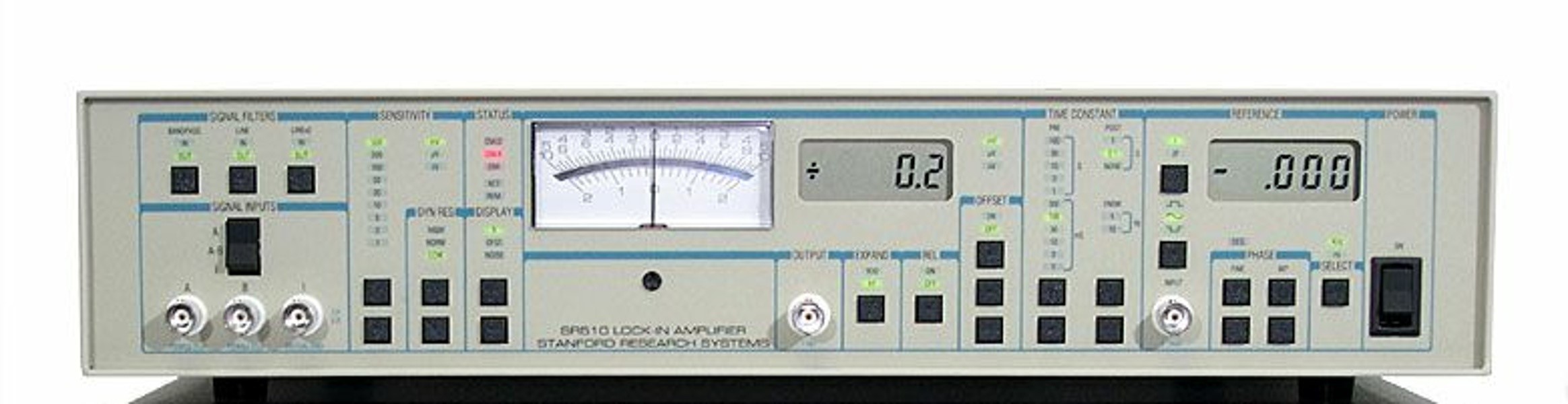
Figure 7: The SR510 lock-in amplifier. Controls for the input signal are on the left, output signal sensitivity and filtering in the center, and controls for the reference signal on the right.