Quantum Analogs
Apparatus
The apparatus you will be using is shown in Figure 4. You will move and replace the column pieces and spacers, then use the function generator to control the frequency and the oscilloscope to view the resonances. The most helpful precaution I can offer is that if you don’t see a clear increase in amplitude as you expect from a resonance condition, then the audio jack on the control box may be lose. Turn the audio jack for the microphone input about a quarter turn and try again. Feel free to ask your TA or technician for help if you’re not seeing the signals you expect.
There are two types of cables in the apparatus: Small, thin wires for the audio connections, and thicker ones with large, metal connectors called BNC cables. Don’t worry about what BNC stands for, it’s the initials of the people the invented this style of cable (called a coaxial cable). BNC connections are the standard for carrying signal from your experiment in your measuring device, so get ready to see a lot of these if (WHEN!) you choose a hands-on career in physics.
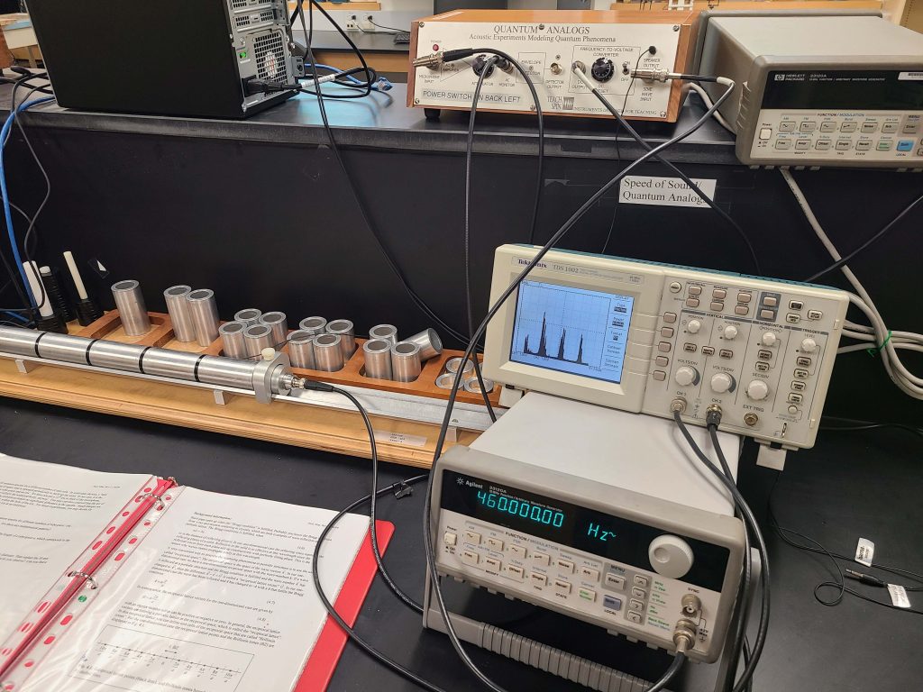
Figure 4: The Quantum Analogs apparatus. Note the cylinder on the left, the sphere on the right, and the control box and PC at the top of the photo. It’s very unlikely that you will have to adjust anything on the control box.
Function Generator
The function generator supplies a variable frequency that is used to drive the speaker and generate sound at one specific frequency. The user sets the amplitude, then uses the left and right arrows to choose which decade of the frequency will be changed, then the knob is used to vary the frequency. Do not go below 500 Hz – there’s no interesting signal at that low a frequency, and too low a frequency can over-saturate the microphone and potentially damage it.
Oscilloscope
The oscilloscope will be used to monitor the microphone output and to record a DC voltage that represents the magnitude of the frequency. There are a few options in the ‘display’ menu that you will find quite helpful:
XY mode – You’re used to using an oscilloscope in YT mode, where the signal from each channel is on the Y-axis and the x-axis is time. An alternate option is XY mode. Now the signal from channel 1 is on the x-axis and channel 2 on the y-axis. The scope cannot save the data when in XY mode.
persist – The persist option let’s you use the scope like an etch-a-sketch. The signal will stay on the scope until the user touches the position or div/V knobs. It’s nice if you want to do a long scan that may not be easily triggered, or if you don’t need to save the data.