Neuron Simulation
Experimental Apparatus
Experimentalists directly probe neurons with nanoamps of current using special tools to avoid destroying the cells. We won’t be probing neurons directly since those types of experiments require a great deal of experience and care to get useful results. Instead, we’ll be using the circuits shown in Figure 2, an Arduino microcontroller to supply the voltages, and an oscilloscope to record the train of voltage spikes that result when the pre-defined threshold voltage is reached. Consider consulting Reference [2], or even just Wikipedia for a great reference for understanding how resistors, potentiometers, capacitors, or MOSFETs work. The circuit you will build and use for the Leaky Integrate-and-Fire model is shown in Figure 3.
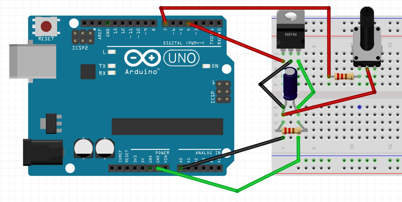
Figure 3: The Arduino Circuit used to simulate a neuron firing. The neuron is made of a 4.7 k resistor and 2200
  F capacitor. An ammeter that measures the current injected into the RC circuit is missing from the figure.
3.1 Current Injection
The digital output pins on the Arduino provide 5 V at a maximum output current of 20 mA. The lower the resistance of the load, the higher the current, which brings us to the most important warning: DO NOT CONNECT THE ARDUINO OUTPUT DIRECTLY TO GROUND! A wire has functionally zero resistance, and the digital output will be damaged beyond repair if its output is shorted to ground. The output from pin 7 in Figure 3 goes to a 250 resistor, then to a potentiometer. In this setup, even with the potentiometer set to 0 , the current draw from the Arduino will never be more than about 20 mA. Increasing the resistance of the potentiometer will decrease the current that reaches the circuit. Use an ammeter between the potentiometer and the RC circuit (not shown in Figure 3) to measure the input current injection. Note that the current will change when the ‘neuron’ discharges. To get a reliable measure of the current, set the threshold voltage in the Arduino code to greater than 5 V.
3.2 Discharge at Vth
The voltage across the resistor in the RC circuit is measured using one of the analog input pins of the Arduino. A predefined voltage threshold is set in the Arduino program, at which point we would like the capacitor to discharge, thereby simulating the firing of the neuron. We accomplish this discharge using a MOSFET. A MOSFET (shown in Figure 4) is a piece of layered semiconductor that acts as a voltagecontrolled switch. When voltage is applied to the gate, charge carriers can flow between the source and drain. So when the voltage reaches  , the Arduino sends 5 V to the MOSFET gate, which closes the switches shown in Figure 2A, B, and C, allowing the capacitor to discharge through the resistor.
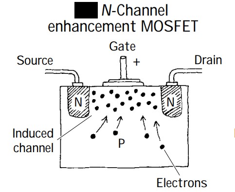
Figure 4: This experiment uses the IRL510 – an N-channel enhancement MOSFET. The drain-source channel is inherently resistive. When a positive voltage is applied to the gate, electrons migrate into the channel and allow current to flow. Figure from Reference [2].
3.3 Oscilloscope
The Arduino microcontroller is great at running looped programs and sending and controlling outputs and timings and lots of tasks along those lines. The Arduino is absolutely horrendous at displaying or storing data; it just wasn’t designed to do that. To measure our discharge spikes and the timings between them, we’ll use an oscilloscope. Probes are attached across the resistor in the RC circuit and connected to channel 1 on the scope, while the ‘trigger’ pin is connected to channel 2 and acts as a trigger signal for the scope to start taking data. The scope has measurement functions to measure the frequency/period of the input signal, or one can use the cursors to manually measure the time between voltage spikes.
3.4 Pulse-Width Modulation
In order to simulate the adaptive nature of neurons, the circuit needs a component with a variable conductance. By applying less than 5 V to the gate of the MOSFET, the number of charge carriers between the source and the drain is reduced, thereby decreasing the conductance through the MOSFET.
The Arduino doesn’t naturally have an analog voltage output, so we’ll have to make our own. The Arduino does have some channels that can be pulse-width modulated. This output is rapidly switched (modulated) between 0 and 5 V so that the average signal is less than 5 V. The Arduino code uses an integer between 0 and 255 to control the modulation frequency of the PWM output, 0→0 V and 255→5 V.
The PWM output is low-pass filtered and passed through an operational amplifier to take advantage of its high input impedance and to protect the Arduino, thereby providing an analog-voltage output from the PWM pin.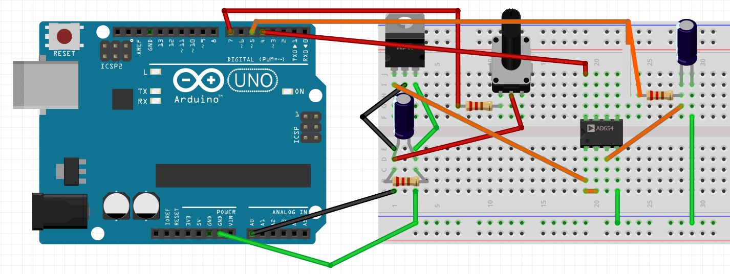
Figure 5: The output of the operational amplifier provides an analog voltage, which is used to control the conductance through the MOSFET.