Cloud Chamber
Procedure
4.1 Testing a TEC
You will use a spare TEC and power supply to test their limits before using them in the cloud chamber.
- Make sure you have the base plate, TEC, temperature sensor, and thermal paste shown in Figure 5.
- Use a wooden stick to spread a THIN layer of thermal paste to the bottom side of the TEC (the printing should be facing up). Place the TEC on the baseplate with the thermal-paste-side down.
- Push down on the TEC so that the paste on the bottom spreads out. You can rotate it a bit left and right to help spread the paste out.
- Get a small piece of Kapton tape and tape the thermocouple to the top of the TEC. Kapton tape remains stuck even when frozen!
- Turn on the thermocouple reader and make sure its reading makes sense (i.e. close to room temperature). Record this value
- Turn on the power supply. Turn the voltage to 2 V and record the voltage, current, and temperature reading (take the temperature reading after 3-5 minutes of setting the power supply. It may take longer than that to get to the true equilibrium value, but we have better things to do with our time.
- Increase the voltage in steps of 2 V until you reach the maximum allowed voltage (16 V). You will need to produce a plot of power vs temperature, so make sure you have the data you will need to do that.
- Can you explain why the temperature changes the way it does as a function of applied power?
- Turn the voltage from the power supply down to 0 V, then turn off the power supply. Continue monitoring the temperature of the cold side of the TEC. Does the temperature rise above room temperature? Why might that be?
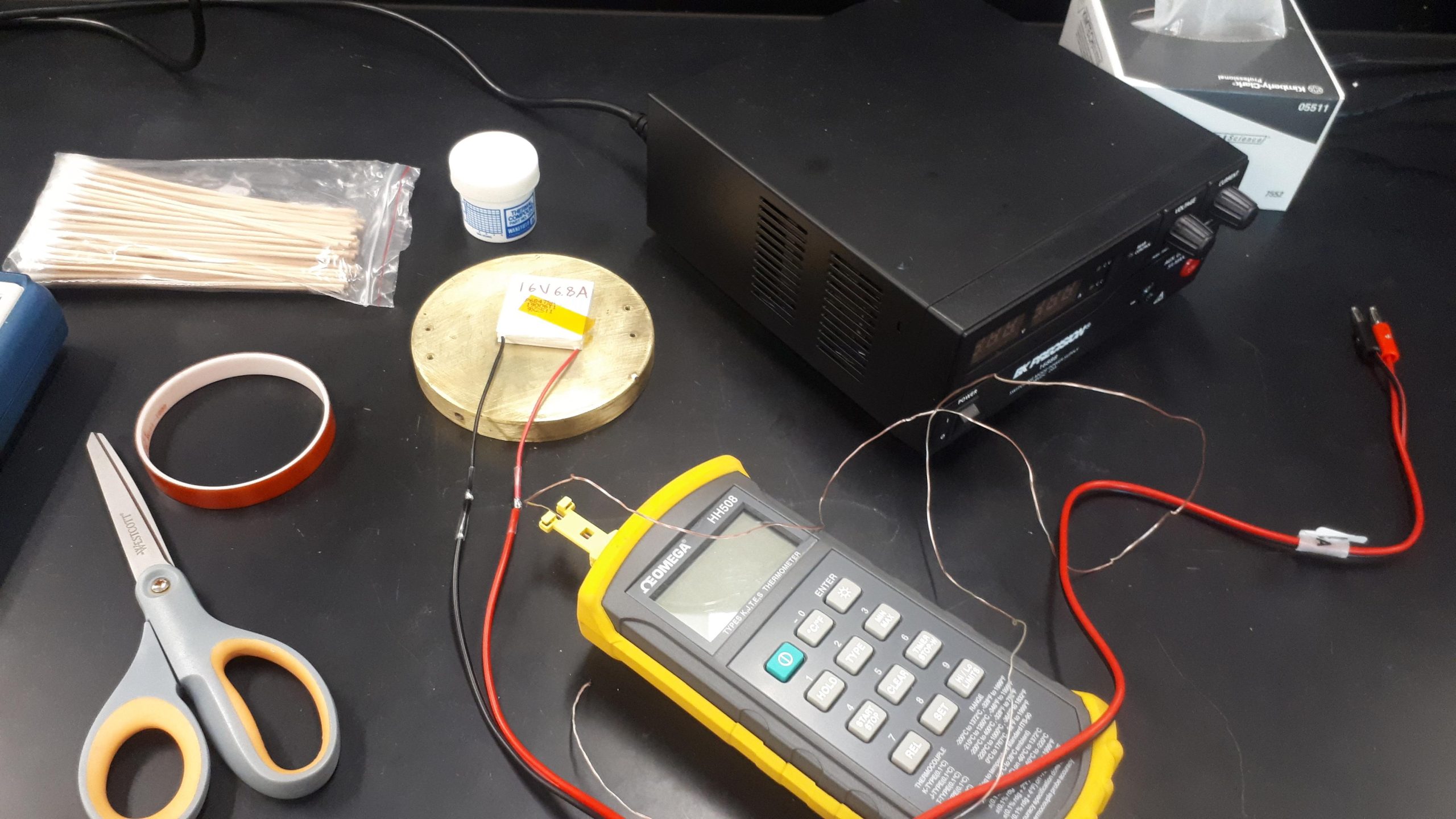
Figure 5: Spare TEC and power supply to play with.
4.2 Before you Begin
- Identify the power supplies and what they power. Getting these settings mixed up can destroy components of the apparatus.
- Measure the length of tungsten rod with a caliper. You’ll need it to calibrate some of your results.
- Make sure the red LED on the HV supply is off and the control box is set to ‘discharge’. (We’re making sure there isn’t any high voltage for anyone to accidentally touch).
4.3 Turning on the Cloud Chamber
- PUT ON SAFETY GLASSES. Remove the top lid of the cloud chamber and soak the pad in isopropyl alcohol. You’ll want a lot of isopropyl here, like, A LOT A LOT; you need to saturate the pad but avoid using so much that there’s alcohol dripping everywhere. Ask the TA if you need more isopropyl alcohol. CAUTION: Do not soak the camera in the center of the top lid.
- Ask the TA or technician to place the
 alpha source in the cloud chamber. You are not allowed to handle the lead source.
 - Secure the top of the cloud chamber using the spring-loaded clamps. Use the webcam and check that you still have a clear view of the bottom of the cloud chamber.
- Turn on the power supply that controls the cooling fan and LED lights. The cooling fan must be turned on before voltage is sent to the TEC.
- Turn on the power supply that provides voltage to the TEC. Set the current to 8.5 A and the voltage to 16 V (in that order, if not already set). The voltage will be set up across the TEC and the black plate in the cloud chamber will begin to cool.
- It takes 10-15 minutes for the plate in the cloud chamber to cool to about −40◦C so that the isopropyl vapour is visible and particle tracks can form.
- Flip the switch on the control box to ‘Apply HV’. Then turn on the high voltage supply. YOU ONLY HAVE TO TURN IT ON FOR A SECOND! The power supply is basically a charged capacitor, and it will stay at high voltage until it’s safely discharged.
- Hopefully you start to see A LOT of particle tracks due to alpha radiation, indicating that the apparatus is working.
- Turn off the high voltage and flip the switch on the control box to ‘discharge’. Ask the TA/technician to remove the alpha source.
4.4 Alpha Particles from Thorium Decay
- Use tweezers to place the piece of thoriated tungsten in the cloud chamber. Close up the apparatus and apply the high voltage. Hopefully you still have enough isopropyl alcohol to generate the saturated layer.
- Once you are consistently seeing particle tracks, open OBS to start recording from the webcam. The record button is near the bottom right of the interface. A 10 minute video should be sufficient. Ideally, you’ll have something like 20 tracks or more to analyze.
- The file will be saved to the ‘Videos’ folder and automatically named with a timestamp. Go and give that file an appropriate name now.
4.5 Measuring Background
- Make sure the high-voltage supply is turned off. Flip the switch on the control box to safely discharge the high voltage.
- Remove the lid of the cloud chamber and move the metal grid out of the way. Use the tweezers to remove the piece of thoriated tungsten.
- Put the metal grid back in place and put the lid back on. Wait a few minutes for the isopropyl vapour to return.
- Once you see a particle track, start recording. We are measuring alpha particle decays from radon in the atmosphere and the rate is not terribly large (thank goodness). Record long enough to get at least ten events.
- It’s sometimes hard to see any background alpha particles and is mostly a luck thing. If you don’t see any after about 15 minutes, just start recording. Remember that even if you see zero tracks, the uncertainty is not zero.
4.6 Saving and Analyzing Your Data
- You can save your recordings onto a USB stick to open at home or on your laptop, or your TA or lab tech can share them through Teams since they’re likely too big to email.
- For the ‘Add to your Report’ objectives, you will likely want to open these video files in ImageJ – specifically FIJI (which is just ImageJ with plugins pre-installed). Download that free program and install FFMPEG from here. Download the most recent version and remove the timestamp from the file type so that it’s just a ‘.jar’. Then you can use FIJI to install that plugin. It may ask you to restart FIJI a few times as it installs other necessary packages. Once that’s done, you can import the .mkv file that OBS generated and look at each frame of the video to measure track lengths.