Torsional Oscillator
Procedure
4.1 Setting up the apparatus
- Ensure that the power-indicating LED is lit up. If not, turn on the apparatus using the power switch at the back.
- Tie the fishing line to one of the pulleys, then string it around the rotor according to Figure 3, and tie it to the other pulley. Does it matter if the pulleys are not at the same height?
- With the pulleys attached to the rotor, gentle rotate the copper disk a small amount. The system should rotate as the pulleys oscillate up and down in a very satisfying manner.
- Run the LabView program from the PC. You should be able to see the sinusoidal oscillations in the LabView program.
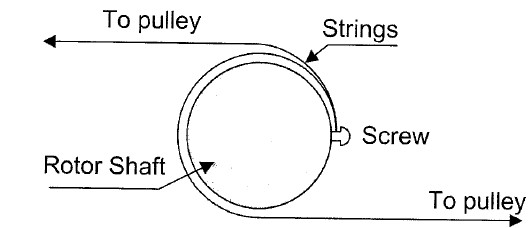
Figure 3: The apparatus used to measure thermal conductivity of gases. The two cylinders are located in the bell jar assembly.
4.2 Calibrating the Position Transducer
- Connect the power supply to the terminals at the bottom of the torsional oscillator apparatus. You are going to rotate the disc by applying current to an electromagnet which interacts with a permanent magnet on the rotor.
- Before turning on the power supply, make sure the voltage is set to maximum and the current is set to zero. Record the voltage from the position transducer as well as the angle of the disk from the ruler on its circumference.
- Apply approximately 2 A – or some value that will rotate the disc to an easily-read angle. Record the voltage from the position transducer. Turn the current back to zero.
- Swap the leads from the power supply to rotate the disk the opposite way. Apply approximately 2 A again; the disc should rotate in the opposite direction. Record the angle and the voltage from the position transducer.
- Repeat the steps above a few times. We use this range to avoid any hysteresis in the torsion fiber that may arise from only using it in one direction repeatedly. Use the average of your measurements as a calibration factor for the position transducer voltage.
4.3 Measuring the Torsional Constant
- Note that your calculations of rotational inertia will use your measured value for the torsional constant. Take your time to be sure that you have a reliable measurement.
- With just the pulleys on both sides of the string, note the reading of the rotated angle using the angular displacement scale on the copper disk. Ideally, this reading would be exactly zero, but it probably won’t be.
- Starting with the smallest mass, add mass to both sides of the pulleys to apply a net torque. What is the magnitude of the torque you’re applying? Usually, one would use
 . Look at the string across the rotor and gravity to determine your torque value. Talk to your TA if you’re not certain.
 - Note the angular displacement due to the gravitational force of the smallest mass.
- Continue adding mass to the same pulley and recording the angular displacement. Avoid using the 400 g mass. If you were clever, you could use some mass on the other pulley to get more data points.
4.4 Rotational Inertia of a Disk
- Remove the masses from the pulleys.
- Start the LabView program so that it is recording the angular displacement of the copper disk.
- Pull one of the pulleys so that the disk rotates a specific number of radians, then release it. You should see a sinusoidal pattern in the LabView program. Looking at the graph in the program, estimate the period of rotation and its uncertainty.
- Pull one of the pulleys so that the disk rotates to a different number of radians, then release it. Again, record the period.
- Record at least 5 values for the period. They don’t all have to be at different starting rotational displacements, but you definitely need to check if the starting amplitude affects the period (should it?). You could also check to see that the period is mostly constant as the rotational amplitude decreases over time.
4.5 Rotational Inertia the Brass Quadrants
- Add brass quadrants to the copper disk, and take new measurements of the period of rotation. The two arrangements you must use are to have four quadrants in a circle around the rotor, then to have two pairs of stacked quadrants that form a tall semi-circle.
- Feel free to experiment with any other arrangement you can imagine, presuming you have time left in the lab.