Gas Thermometry
Experimental Apparatus
The apparatus consists of a table divided into two experiment stations as shown in Figure 1. Each station has three reservoirs underneath the table, the ones at the ends contain a tall metal heating vessel on a hot plate. The power is controlled from the variable autotransformer (a.k.a. ‘variac’) in the corresponding corner of the table. The middle reservoir contains a polypropylene cylinder placed into a large Styrofoam block for insulation and contains a near equilibrium mixture of ice and water. The centre-most reservoir is also a polypropylene tube in a Styrofoam block but this tube contains liquid nitrogen. Each of these acts as a stable temperature reference and are accessible through a flange covering a hole in the table.
The main piece of the apparatus is a thermometer which consists of a steel gas vessel attached to valves and tubing and mounted to a lexan sheet (to prevent splashing/steam/vapour and to protect the manometer), a digital manometer and a handle. The thermometer is designed to fit into each reservoir and rest on the flange on the lexan sheet. The tubing/valving unit is designed to minimize the amount of dead-space that is not at the prescribed temperature.
A close-up of the control valves is shown in Figure 2. Valve ‘A’ is a two-way valve that can be turned to allow the vacuum to act on the thermometer or allow gas to enter. Turning the valve vertical isolates the gas thermometer. The vacuum pump is used to evacuate the vessel before filling it with a known gas at a known pressure. Valve ‘B’ is a needle valve (or throttle valve) that allows the controlled slow filling of the thermometer to the desired pressure. When you are not filling or evacuating the cylinder, keep valve ‘A’ in the closed position, with the handle aligned vertically.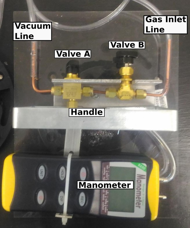
Figure 2: Control valves used to evacuate and fill the gas thermometer.
To evacuate the cylinder, turn on the vacuum pump (the switch is at the back, near the power cord) and the manometer. Turn the handle of valve ‘A’ so that the valve indicator points left to the vacuum tubing connection. Watch the manometer pressure until it stabilizes at the base pressure. Turn valve ‘A’ to the vertical closed position. The throttle valve ‘B’ is connected by a long tubing run to the gas cylinders at the opposite side of the room. The tube connection to the throttle valve is purposely made leaky so that the gas in the tubing run is replaced with fresh gas from the cylinder to ensure that the intended gas is loaded into the cylinder.
The manometer has a digital readout screen. It is suggested you use Torr or mmHg as your unit of measurement, but it is not necessary if you make the appropriate conversions. Note that like most pressure gauges, the manometer reads in gauge pressure, meaning pressure relative to the outside atmosphere. Atmospheric pressure in the lab changes with the weather patterns and with the buildings HVAC system. A barometer is provided in the lab and should be used to convert these measurements to absolute pressure.