Cloud Chamber
Experimental Apparatus
The key components of the apparatus is the super-saturated isopropyl alcohol. The entire apparatus, shown in Figure 2, exists only to create and monitor this layer of super-saturated isopropyl. We need a very cold surface, a way to view the alpha-particle tracks, and an electric field to keep the particles in our supersaturated layer.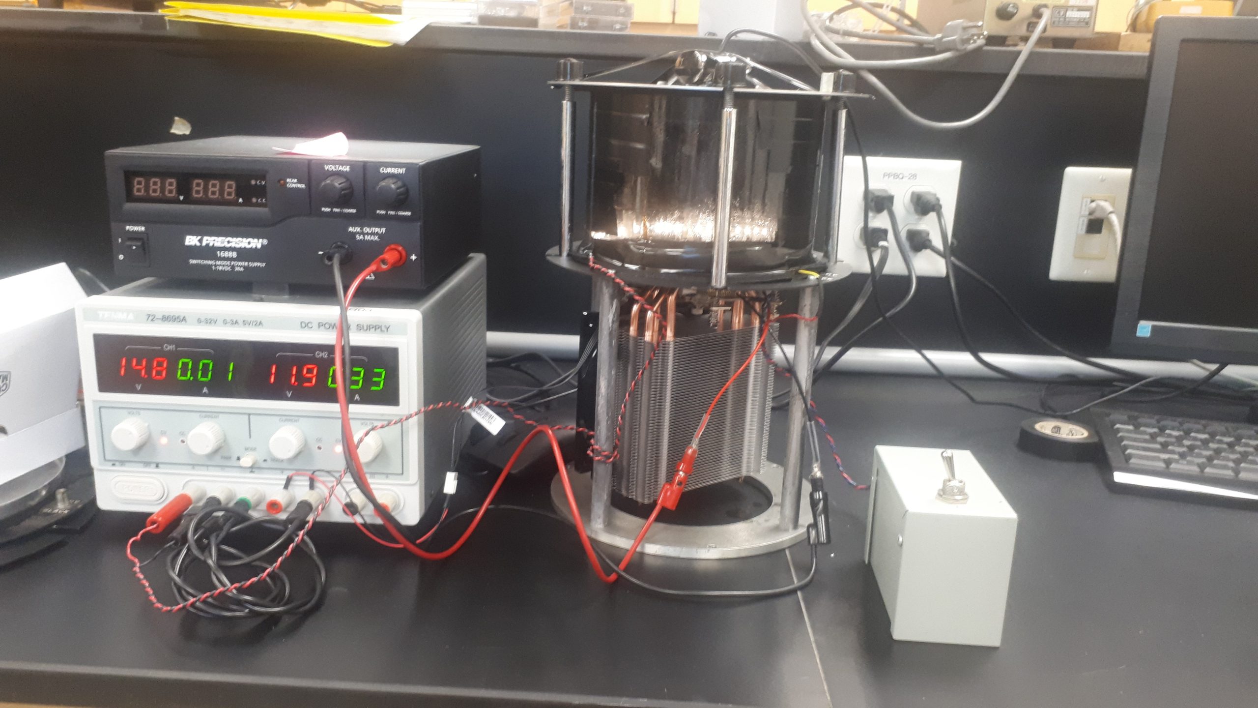
Figure 2: Cloud chamber apparatus.
3.1 Thermoelectric cooler
Thermoelectric coolers (TECs) operate based on the Peltier effect, whereby current is made to flow through a junction of two conductors and heat can be generated or removed. For this experiment, your TEC is made of a series of p-n junction semiconductors. When a DC current flows through the series of p-n junctions, as shown in Figure 3, it generates a temperature difference.
3.2 High-Voltage Supply and the Electric Field
The alpha particles from radon or thorium decay are created isotropically, which puts our relatively short detection volume at a disadvantage. To help compensate, we apply a high voltage that will force ions lower in the detector and increase the number and density of our particle tracks. This HV power supply is derived from an electric fly swatter. It’s basically just a capacitor that charges up to about 1000 V. The high voltage can be safely discharged through a resistor using the control box, as shown in Figure 4. Just make sure that you are not applying high voltage while also discharging through the resistor; it’s an efficient way to waste batteries.
With this setup, the high voltage supply is not nearly as dangerous as most research-grade HV supplies have potential to be, but it can give a surprising shock if you open up the apparatus without discharging the supply. From personal experience, I can tell you that it’s about as uncomfortable as a bee sting.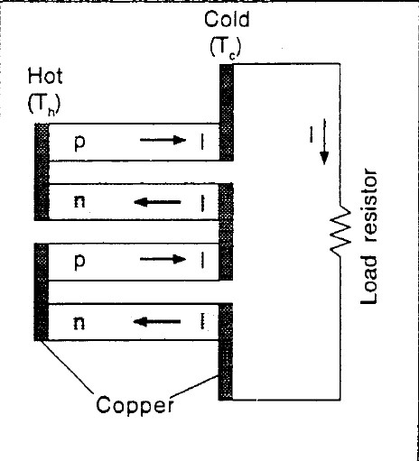
Figure 3: Example schematic of the p and n junctions in a thermoelectric cooler. Note the direction of the current and temperature difference.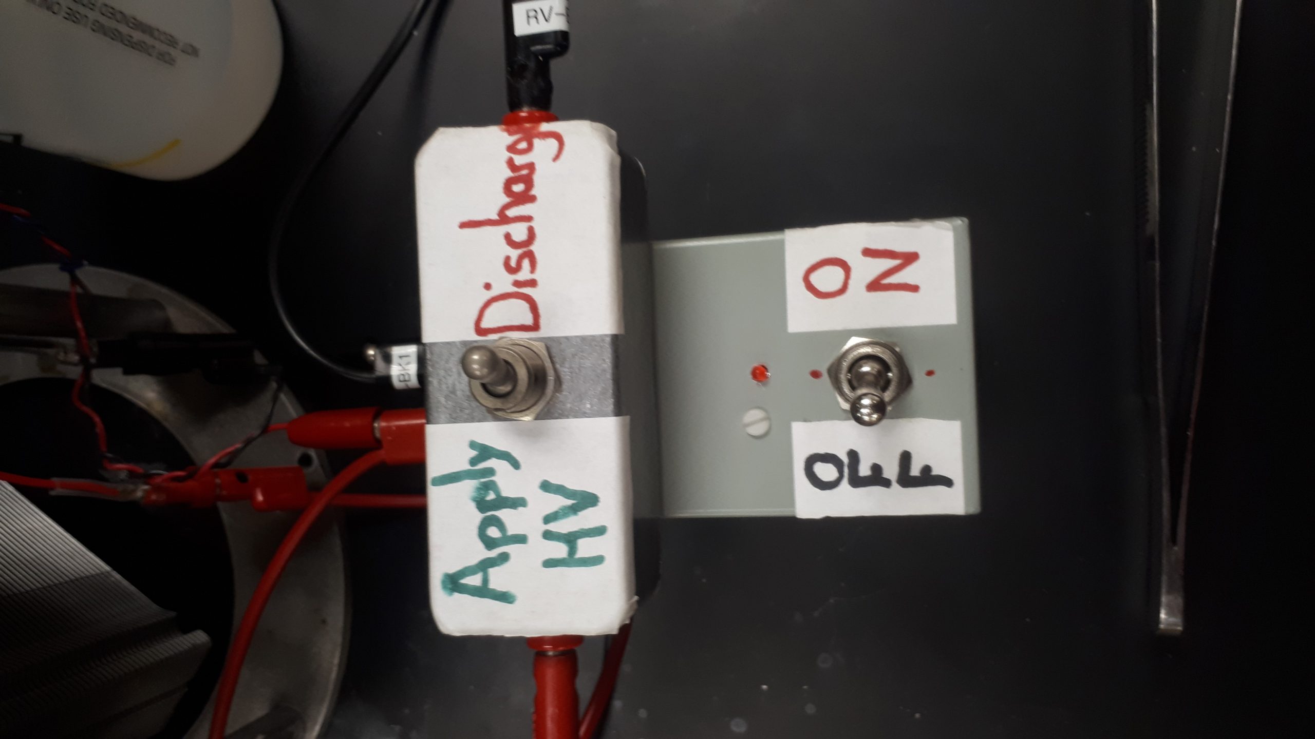
Figure 4: High voltage power supply and control box. Be mindful of the state of each of these switches.
3.3 Camera
A webcam is mounted to the top-plate of the cloud chamber. Please be careful with the cable to the camera when removing and replacing the top-plate of the cloud chamber. The lens of the camera has been adjusted to focus on the sample of thoriated tungsten. By measuring the length of the sample with a caliper, the user will be able to convert the scale of the video feed to units of mm instead of pixels.
Please keep in mind that we are making some geometrical assumptions in these calculations. We are assuming that the entire bottom-plate is the same distance from the camera, and ignoring the small angle from the camera center to the edges of the bottom-plate. We are also going to ignore the z-component of the track-length. We can’t measure depth from just this one camera, so we’ll note that assumption and be clear that we are measuring the minimum track length.