Modern Interferometry
Experimental Apparatus
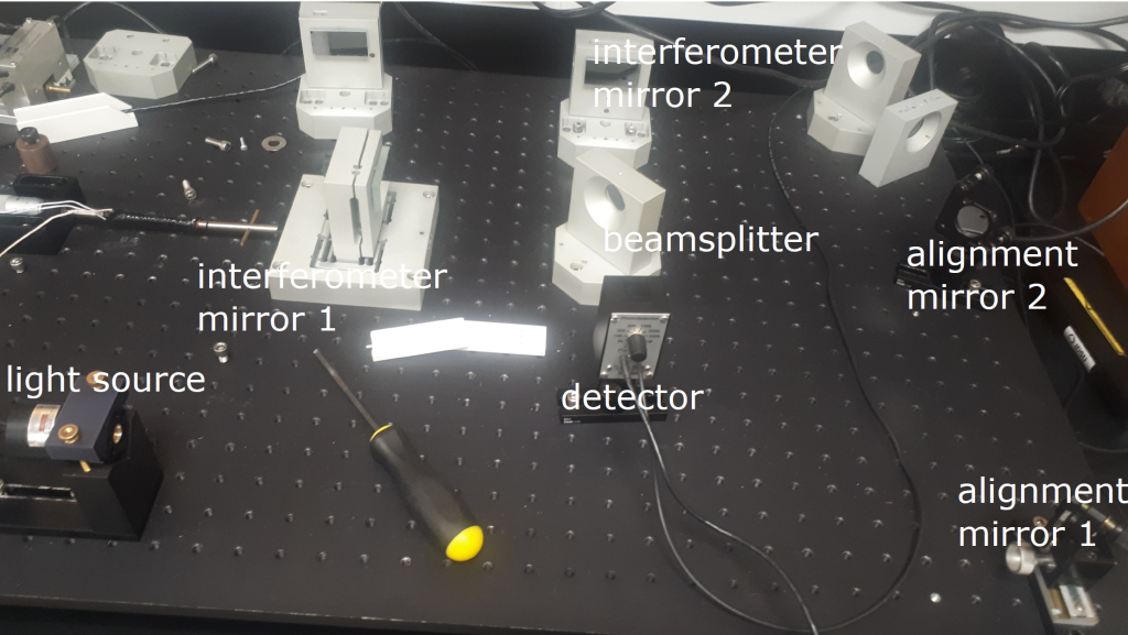
The apparatus is shown in Figure 2.
3.1 Light Sources
The physics of these light sources is not terribly relevant to the interferometer. Interested students are directed to Wikipedia to learn more about helium-neon lasers or diode lasers. The most important information for you here is that the helium-neon laser operates at 632.8 nm and the diode laser operates at 650 nm.
3.2 Optical Components
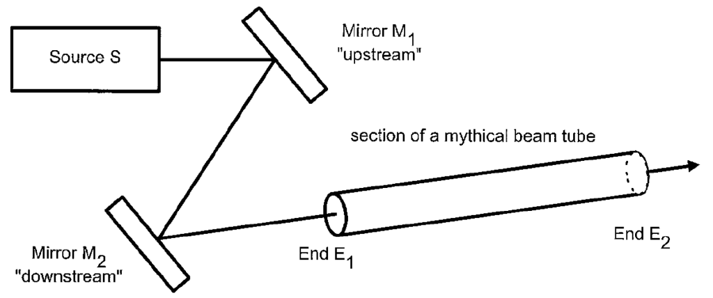
The two mirrors used to align the laser beam into the interferometer have knobs to control the horizontal and vertical tilt of the mirrors. With just two mirrors, one can control both the position and angle of the input
beam to the interferometer (see Figure 3). Note that nearly every laser light source should be accompanied
by two mirrors so that the user can completely control the position and angle of the beam.
The beam splitter in this interferometer is a metal film beam splitter. A thin coating of aluminium is deposited onto a glass substrate. The coating is so thin that it reflects only half of the incoming light, allowing the other half to pass through, thereby splitting the incoming beam into two outgoing beams of equal intensity. Note that there are many ways to split laser beams, this just happens to be the one we are using.
The photodiode generates a small current when exposed to light. This current is passed through a resistor to generate a voltage that can be measured using the oscilloscope. The photodiodes that accompany this apparatus have a dial on the back where the user can choose a resistor value that will maximize the voltage output of the photodiode, but avoid saturating the detector.
3.3 Motor and Differential Micrometer
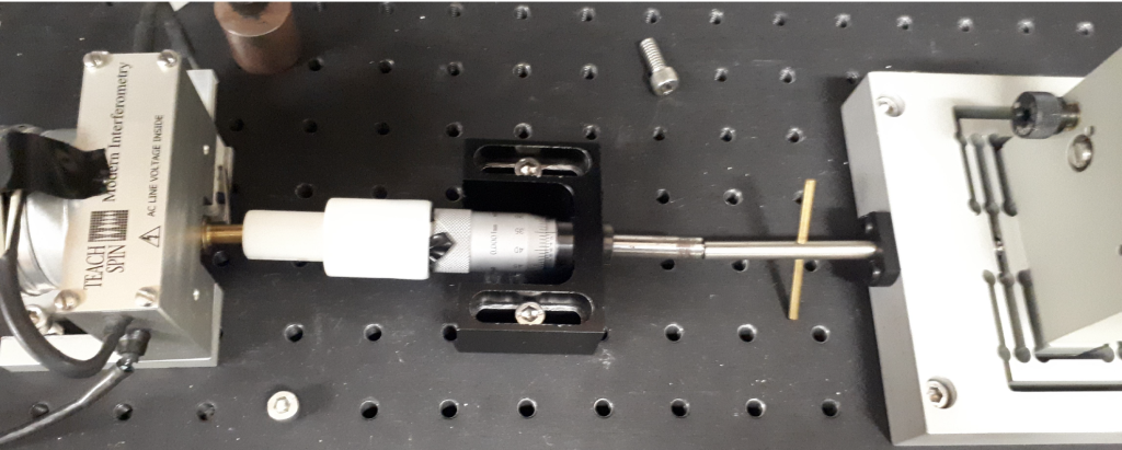
One of the mirrors of the interferometer is mounted on a precisely-machined, spring-loaded stage. A motor turns the handle of a rotary caliper, which pushes the stage a very small, but very precisely measured, distance. See Figure 4.
In order to precisely measure the wavelength of the light source, you will need a precise measurement of the distance that the mirror of the interferometer has moved. This precise measurement is achieved using the differential micrometer shown in Figure 5 and explained in Appendix F of the TeachSpin manual in the lab. Reading the differential micrometer is much like reading a typical caliper. There is a short video here that explains how to read the scale and has an example measurement.
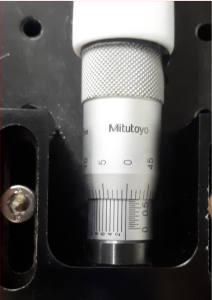
shaft.
3.4 Control Box
The front panel of the control box is shown in Figure 6. Follow the lines that show how the input signal from the detector is processed. Please note the location of the light source power switch, the DC offset knob, and the low-pass filter.
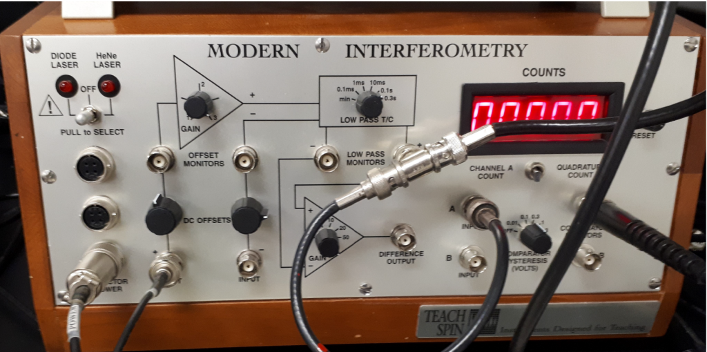
The main function of the control box is to take the sinusoidal signal from the detector and count the number of peaks that pass in a given time interval. This goal is achieved by using a comparator. A comparator takes two analog inputs (the detector output and the DC offset voltage) and provides a digital output (either high or low) depending on which input is higher. This way, the analog signal from the detector is converted to a square wave digital signal, where the square waves can be counted.
3.5 Material Samples
You will be measuring the thermal expansion coefficient for various samples. The samples have been wrapped in a resistor. When current is pushed through the resistor, the temperature of the sample increases. A thermocouple is added so that the temperature can be monitored.