Charge to Mass Ratio
Experimental Apparatus
Figure 1(a) is a sectional view of the tube and filament assembly, and Figure 1(b) is a detailed section of the filament assembly at right angles to Figure 1(a). Figure 2 is a schematic of the electrical circuit used to heat the filament, bias the anode, and send current through the Helmholtz coils.
3.1 Electron Beam
The beam of electrons in the tube is produced by an electron gun composed of a straight filament surrounded by a coaxial anode containing a single axial slit. The electrons are accelerated by a potential difference between the heated filament and the anode. Mercury vapour in the vacuum chamber is ionized by electrons with more than about 10 eV of kinetic energy. The mercury ions and electrons recombine, emitting a bluish glow in the path of the electrons.
The filament of the  tube has the proper electron emissions when carrying 3.5 to 4.5 amps. Exceeding 4.5 amperes will materially shorten the tube’s life. Good results can be obtained using an accelerating voltage of 20 to 45 volts. An electron emission current of 4 to 6 ma gives a visible beam. For maximum filament life, operate the tube with the minimum filament current necessary for proper electron emission. It is helpful and good practice to apply about 20 volts accelerating potential to the anode before heating the filament. Always start with a low filament current and carefully increase it until the proper electron emission is obtained. Since the electron beam appears suddenly it is advisable to increase the filament current slowly to avoid overheating and possibly burning out the filament.
The electron trajectory indicated by the mercury vapour can be difficult to accurately measure. The apparatus includes a cross bar with vertical wires coated in a material that fluoresces when struck by an electron. The distances between the filament and the far edge of the vertical wires are given in Table 1. Note that this is the DIAMETER of the circle inscribed by the electron.
3.2 Helmholtz Coil
The magnetic field of the Helmholtz coils causes the electron beam to move in a circular path, the radius of which decreases as the magnetic field increases. By proper control of the magnetic field, the sharp outer edge of the beam can be made to coincide with any one of five bars spaced at known distances from the filament.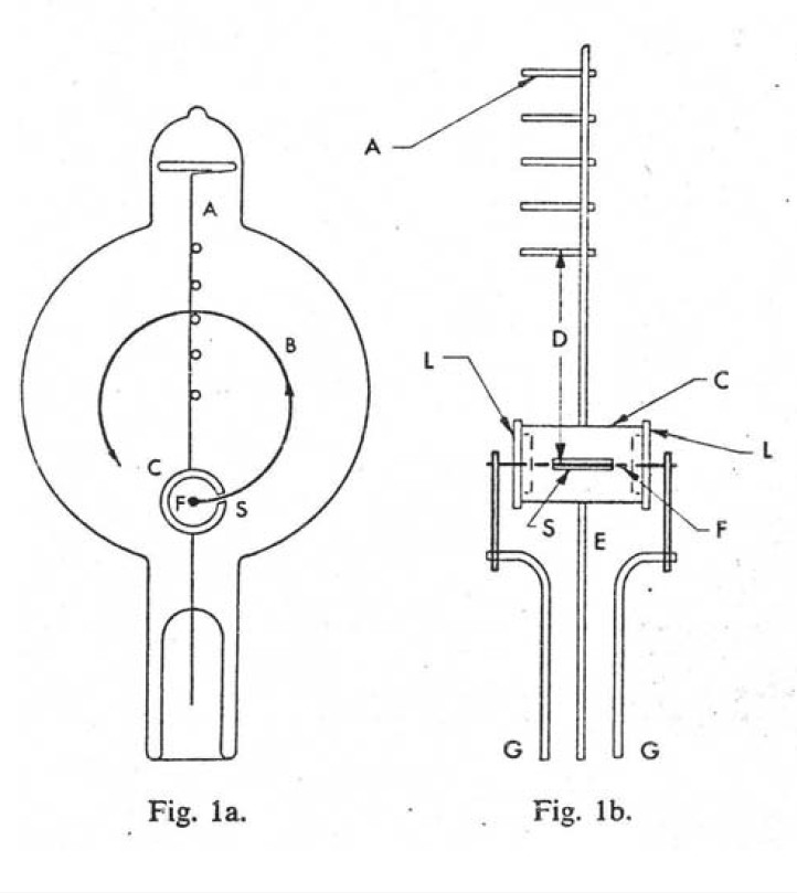 Figure 1: Cross sectional view of the apparatus on the left and a detailed view of the electron filament on the right. The labelled components are A. Five cross bars attached to staff wire. B. Typical path of beam of electrons. C. Cylindrical anode. D. Distance from filament to far side of each of the crossbars. E. Lead wire and support for anode. F. Filament. GG. Lead wires and supports for filament. LL. Insulating plugs.
Recalling Equation (4) we can create an equation that relates the charge-to-mass ratio of the electron to the variables we can control with this specific apparatus:
(5) 
where the term in parenthesis is constant for any given Helmholtz coil setup. This particular pair of coils has 72 turns of copper wire ( ) and a mean radius of 33 cm (
 ). Knowing the settings for
  and
and  , one can measure the radius of the electron trajectory
  and compute the charge-to-mass ratio of the electron.

Figure 2: Schematic of the circuit used to heat the filament, accelerate electrons, and power the Helmholtz coils.
|
Crossbar Number |
Distance to Filament (m) |
|
1 |
0.0648 |
|
2 |
0.0775 |
|
3 |
0.0902 |
|
4 |
0.1030 |
|
5 |
0.1154 |
Table 1: Distances from the electron filament to the outer edge of the vertical wires of the crossbar