Brewster’s Angle
Procedure
5.1 Exploring Polarization
- Arrange the Transmitter and Receiver in a straight line, with each component between 10 and 20 cm away from the center. Set the reading on Receiver to near full scale.
- Loosen the hand screw on the back of the Receiver and rotate the Receiver through 180
 in increments of 10. Record your measurements.
 - Reset the components so that the Receiver and Transmitter are in a straight line and at 0 (the horns should be oriented with the longer side horizontal).
- Place the polarizer on the track near the Transmitter
- Record the meter reading when the polarizer is aligned at 0, 22.5, 45, 67.5, and 90 with respect to the horizontal. There are no angle markings on anything, so get the best accuracy you can by eye.
- Remove the polarizer and rotate the Receiver 90. Record the meter reading.
- Replace the polarizer and repeat the measurements from the previous steps.
- Plot your data. Are you convinced that the microwave source emits polarized electromagnetic waves?

Figure 4: (a) A wave moves from a medium of low index of refraction to high index of refraction in the least interesting way possible. (b) A wave moves from a medium of low index of refraction to high index of refraction at an angle. The wave is refracted (the direction of propagation has changed). (c) A pen partially behind a block of acrylic. The apparent position of the object changes due to refraction.
5.2 Measuring Brewster’s Angle
It is incredibly important that the instrument components are well aligned and at the correct angles for this experiment to work.
- Set the Transmitter and Receiver for vertical polarization (90)
- Adjust the polyethylene block so that it is square with the foam pedestal it sits on. The block must be centered on the axis of rotation. Adjust the angle of incidence of the microwaves from the Transmitter to 30.
- Rotate the Receiver to the angle where the detected signal is expected to be (i.e. angle of incidence = angle of reflection). You should have a 60 angle between the Transmitter and Receiver with the polyethylene block oriented so that the angle of incidence equals the angle of reflection. Adjust the Receiver for a mid-scale reading and record that value.
- Rotate the foam pedestal by 2, then rotate the receiver to keep the angle of incidence the same as the angle of reflection. Record your measurement.
- Continue in this manner until you have measurements every 2 until you reach 70 or go beyond full scale of the Receiver. Can you determine Brewster’s angle from your data?
- Set the Transmitter and Receiver for horizontal polarization (0)
- Adjust the angle of incidence of the microwaves from the Transmitter back to 30.
- Rotate the Receiver to the angle where the detected signal is expected to be (i.e. angle of incidence = angle of reflection). Adjust the Receiver for a mid-scale reading and record that value.
- Rotate the foam pedestal by 5, then rotate the receiver to keep the angle of incidence the same as the angle of reflection. Record your measurement.
- Continue in this manner until you have measurements every 5 until you reach 70 or go beyond full scale of the Receiver. Can you determine Brewster’s angle from your data?
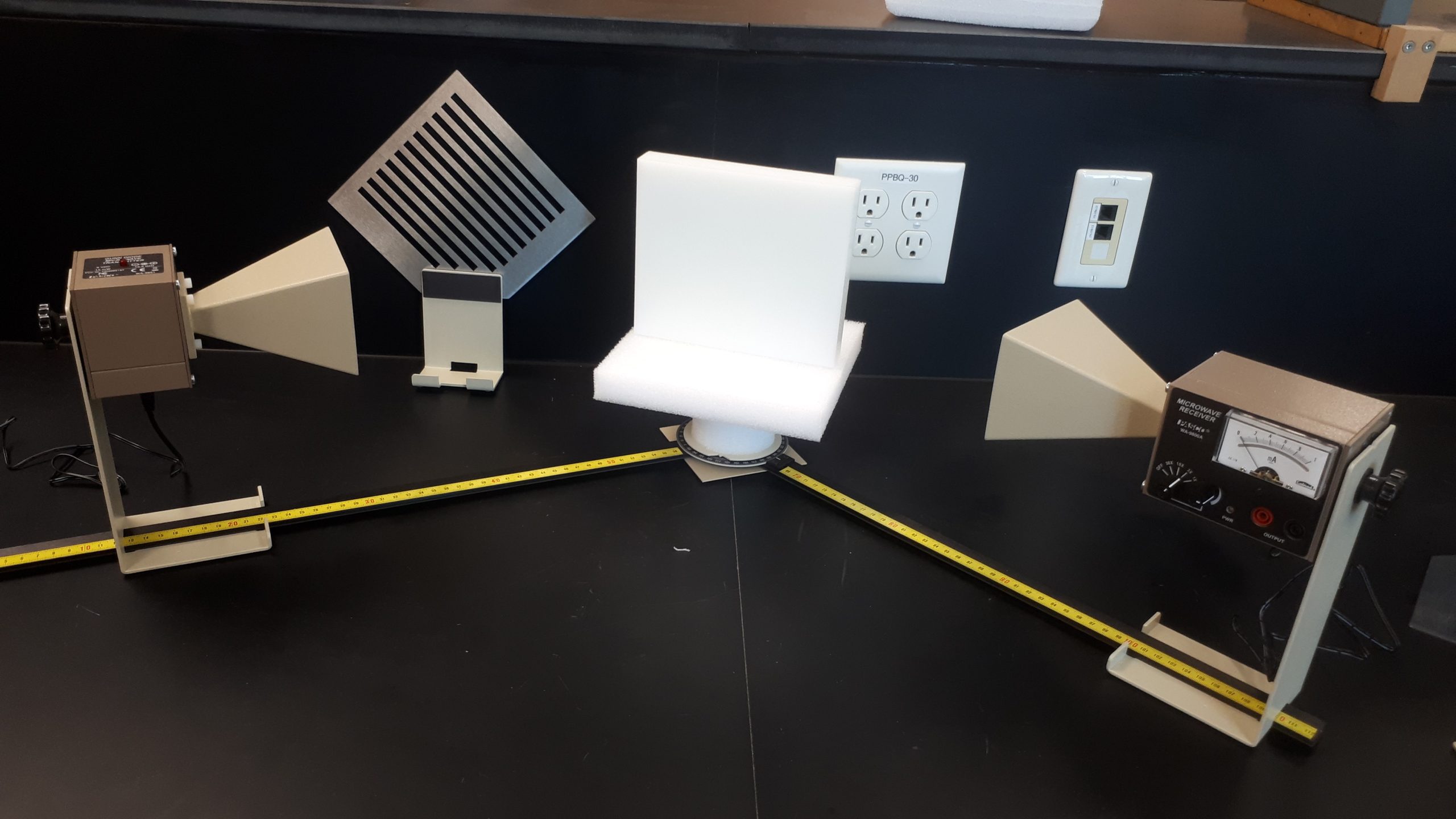
Figure 5: Microwave polarization apparatus. Transmitter on the left, Receiver on the right. The metal plate with the slots cut out is the polarizer, and the white block is the polyethylene.