Brewster’s Angle
Introduction
3.1 Wave Polarization
Electromagnetic waves, such as light or microwaves, are described as transverse waves; meaning that the oscillations of the wave are perpendicular to the direction of propagation of the wave; like surface ripples on water or the strum of a guitar string. In contrast, a longitudinal wave is when the oscillations are in the same direction as the propagation of the wave; like a sound wave or a slinky. See Figure 1 for an illustration of each type of wave.

Figure 1: (a) a longitudinal wave travelling in a spring. (b) a transverse wave travelling in a spring. Image from Ref [1]
Transverse waves are more interesting than longitudinal waves in that they can be polarized. The polarization of a wave refers to the geometric orientation of the wave oscillations. When these oscillations are happening in whatever we decide to call ‘vertical’ or ‘horizontal’, then we would say that the wave is linearly polarized, either vertically or horizontally, as in Figure 2.
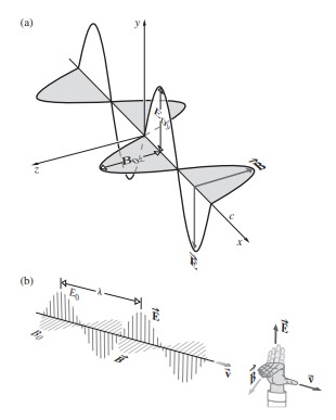
Figure 2: A linearly polarized electromagnetic wave. Image from Ref [1].
Another notation that is commonly used is to refer to the polarization of light as either ‘s’ or ‘p’ polarized instead of using the arbitrarily-decided directions of horizontal and vertical. ‘s-polarized’ light oscillates perpendicular to the plane of incidence, while ‘p’ polarized light oscillates parallel to the plane of incidence, as shown in Figure 3.
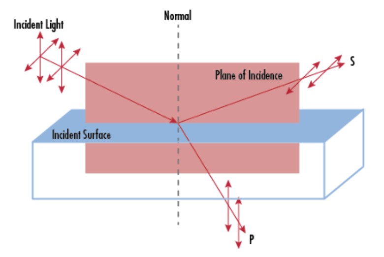
Figure 3: A schematic of ‘s’ and ‘p’ polarization. Image from Edmundoptics.com.
There are two more points worth mentioning about polarized light even though they aren’t completely relevant to this experiment:
- The wave can have some superposition of horizontal and vertical polarizations, resulting in circular polarization. This experiment only explores linear polarization, but circular polarization is incredibly important in atomic physics and surface-defect characterization.
- Electromagnetic waves have electric and magnetic field vectors that are always perpendicular to each other, but we only refer to the electric field when discussing polarization (electricity isn’t special, that’s just convention).
3.2 Incidence, Reflection & Refraction
When an electromagnetic wave passes through the boundary between two media, the speed of the wave changes. When an electromagnetic wave is moving through a medium like air or plastic, the atoms in the material behave like tiny electric dipoles: They are accelerated by the electric field and re-radiate the electromagnetic wave at the same frequency, and in the same direction, but with a slight delay – i.e. the wave slows down. This slowing effect depends on the refractive index ( ) of the material – a perfect vacuum has
  .
.
If the angle of the medium change is perpendicular to the direction of propagation, then nothing interesting happens – the front of the wave experiences the change in medium all at the same time and the direction of propagation remains unchanged (Figure 4(a)). When the medium change is at some angle with respect to the direction of propagation, then the wave experiences the change in medium at slightly different times, from one side of the wave to the other. The wavefront must stay continuous at the boundary, despite the slowing of the wave. The result is that the direction of propagation of the wave is forced to change, as shown in Figure 4(b). This phenomenon is called refraction, and it’s the reason that objects appear to bend when they are partially submerged or behind some higher-index-of-refraction material (Figure 4(c)).

Figure 4: (a) A wave moves from a medium of low index of refraction to high index of refraction in the least interesting way possible. (b) A wave moves from a medium of low index of refraction to high index of refraction at an angle. The wave is refracted (the direction of propagation has changed). (c) A pen partially behind a block of acrylic. The apparent position of the object changes due to refraction.
The angle of refraction is determined using Snell’s law (this law was first described by a Persian scientist in Baghdad in 984 – 600 years before Snell was born). When a wave moves from ‘medium 1’ to ‘medium 2’, as in Figure 4, then the ratio of the sines of the angles of incidence and refraction is equal to the inverse ratio of the indices of refraction:
(1) 
Therefore, if the angle of incidence is known (it’s usually pretty easy to control) and the index of refraction of the initial medium (like air) is known, then we can determine the angle of refraction or the index of refraction of the second medium if we know or measure the other one.
Brewster’s Angle
We’re now ready to combine these ideas of polarization and refraction. And we’ll be focused entirely on ‘p-polarized’ electromagnetic waves. As the polarized light travels through a medium, the oscillating electric field causes the electric dipoles of the material to oscillate in the same direction as the polarization. Here is the really critical part: Dipoles do not radiate energy in the direction of their dipole moment! So if the angle of the new medium can be controlled such that the angle of the refracted light is perpendicular to the expected angle of the reflected light, then ‘p’-polarized light cannot be reflected! If that sentence isn’t quite making sense right now, that’s okay. You’re going to prove this point to yourself experimentally.
Combining the geometrical argument:  and Snell’s law (Equation (1)), then the angle for which no light is reflected is given by
(2) 
which is called Brewster’s angle. When ‘p’-polarized light is transmitted through a medium at its Brewster angle, the result is total refraction and no reflection. This phenomenon can be used to remove unwanted polarizations of light from an imperfectly polarized light source, improve the efficiency of gas lasers, and can be used to study thin films on liquid surfaces using a Brewster angle microscope. Note that all of the mechanisms we’ve introduced here are dependent on the wavelength of the electromagnetic wave: Brewster angle measurements are wavelength dependent.