Planck’s Constant
Procedure
4.1 Understanding the Retarding Potential
- A stand with three magnets (shown in Figure 4) is used to explore the concept of the retarding potential (which is how your detector works).
- WARNING: These neodymium magnets are incredibly strong. If two are pressed together, it is unlikely that we will be able to pry them apart. And worse, if your finger is in between the magnets, then you could be injured – likely a bruise or a severe pinch. Please handle the magnets with care. Please do not remove the loose magnet from its guiding rod.
- The fixed magnets are oriented oppositely to the loose magnet, thereby repelling it.
- Drop the magnet from increasing heights until it has enough energy to overcome this magnetic retarding potential. Use the meter stick to estimate the height (you don’t have to be precise)
- Use the spanner (thin little wrench) to loosen the fixed magnets and bring them either closer or farther away from the center. Tighten the nuts so the magnets are fixed. How do you expect your choice to change the retarding potential? Note the height you dropped the loose magnet from in order for it to overcome the retarding magnetic potential.
- Move the fixed magnets again and see how the retarding potential and the energy required to overcome it have changed.
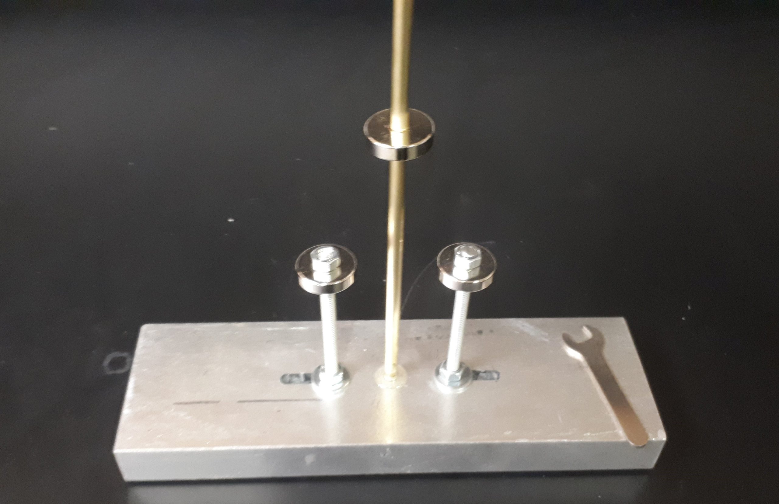
Figure 4: Emission spectrum of mercury
4.2 Mercury Lamp & Alignment
- Ensure that the two light shields on either side of the mercury lamp are in place. Please wear the UV-protection goggles while aligning the mercury lamp. Once the lamp is aligned, and no other adjustments are being made, it is safe to take off the goggles. Put them on again if you are making ANY change to the apparatus.
- Turn on the mercury lamp with the toggle switch located near the bottom of its housing. Please keep the lamp on for the entirety of the lab session. Turning the source on and off again can reduce its operating life, and can cause random fluctuations in it’s output intensity; thereby making the experiment impossible.
- Students should start by checking that the apparatus is aligned. Light that leaves the mercury lamp should be focused by the lens as it passes through one of the filters on the filter wheel, and through the iris. By the time the light reaches the housing of the photocell, it should be focused tightly enough to enter the photocell without clipping on the housing. If small adjustments of the apparatus components do not result in well-focused light at the photocell, talk to your TA.
4.3 Setting up the Retarding Potential
- Connect output1 to input2 using the short BNC cable provided.
- Open the moku app from the PC. Connect to the moku. Take a moment to appreciate how many instruments this device can replicate in software, then launch the oscilloscope.
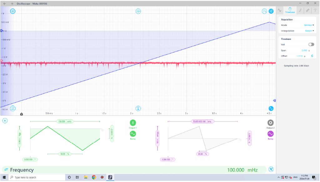
- Open the function generator using the little sine wave near the bottom right of the oscilloscope display.
- Have it generate a ramping potential (triangles). Set the amplitude and offset of the wave to scan as large a voltage range as possible with a maximum output less than 1 V. One half of the ramp should take between 5 and 10 seconds to complete. Be mindful of the units so that you aren’t orders of magnitude off.
- You can use the magnifying glass icon near the top right to set which axis is controlled using the mouse scroll wheel. Click and drag to move the section of the display.
- Open the trigger menu on the right side of the screen. The trigger condition needs to be set to capture one long ramp of the triangle wave. Set the voltage level and whether the signal is increasing or decreasing. If set correctly, the screen should be updating at regular intervals (based on your frequency setting) and the ramping voltage should be nearly identical each time. Your output hopefully looks something like what is shown in Figure 5.
4.3 Setting up the Electronics
- Set the output to `off’. Remove the BNC cable.
- Connect a BNC tee to output1 and connect the sides of the tee to input2 and to the banana-plug cable that goes to the photocathode and anode (using the BNC-plug adapter cable).
- Connect input1 to the banana-plug adapter.
- Connect the red cable from the electrometer to the red side of the adapter. The black side is not connected to anything.
- Connect the black cable from the electrometer to the black port on the multimeter. Your circuit should look something like what is represented in Figure 6.
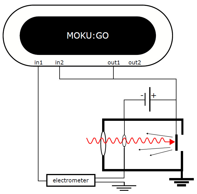
Figure 6: Schematic of the electronics used in this experiment. - Turn the electrometer to `+’. Turn the zero-check knob vertical, which should leave the knob feeling loose. The instrument should already have the large gain knob set to 10-6. You can change the gain setting if the amplitude of the signal is too small or too large.
- Turn on the function generator output from the moku app.
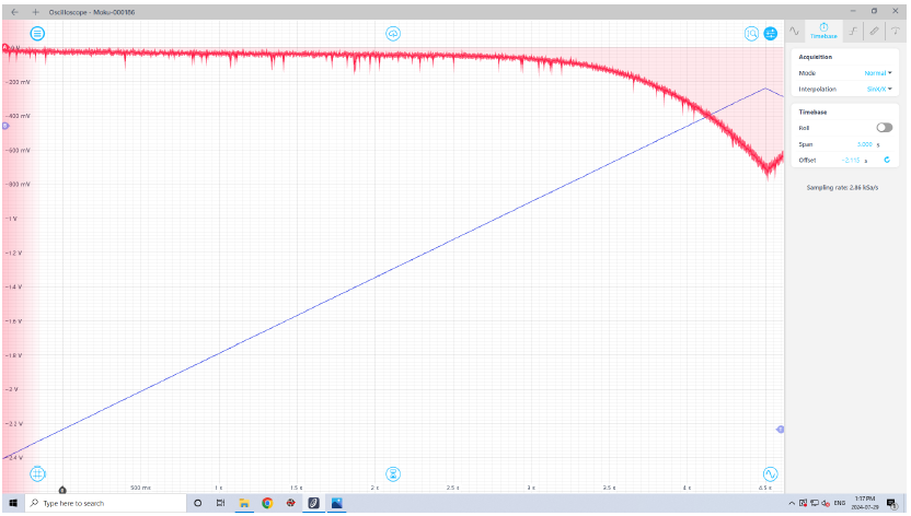
- You should see the ramping voltage that is sent to the anode and photocathode, and a voltage that represents the current generated by the photoelectrons. Hopefully it looks something like what’s shown in Figure 7.
4.4 Taking Data
- Set the filter to your favourite colour (rotating the filter wheel should not affect your alignment).
- The FPGA should be ramping the voltage from negative to positive, and you should see the signal from the electrometer mostly flat but then become negative as the ramp approaches 0 V.
- Once the oscilloscope has completed a full sweep, click the cloud symbol at the top-center of the screen. Give your file a unique name (the file name will also be automatically time-stamped), add comments that you think are relevant and save your data as a file, as shown in Figure 8.
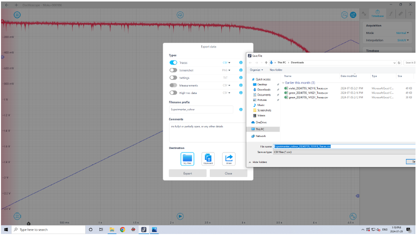
Figure 8: Saving data - Save data for each colour on the colour wheel.
- Adjust the iris to have a much smaller opening. Be sure you can still see the signal from the electrometer. Repeat your measurements for every colour on the colour wheel.
4.4 Finishing Up
- When you are finished with the electrometer, Turn the `ZERO CHECK’ knob to be horizontal. Set the control knob to from `+’ to `OFF’. DO NOT TURN THE KNOB ALL THE WAY TO `POWER OFF’. Plain old `OFF’ will do just fine.
- Turn off the PASCO mercury lamp. The lamp cannot be turned on again while it’s hot, so be sure that you really have all of the data you need before turning off the lamp.