Lab 2: Wheatstone Bridge
Procedure
4.1 Voltage Divider
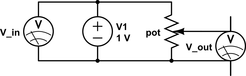
Figure 6: A simple voltage divider with a potentiometer to control the output.
- Make the circuit shown in Figure 6. Use the PASCO Universal control as the voltage source.
- Open the Capstone software and find the ‘signal generator’ tool (usually on the left side of the screen). Under ‘waveform’ choose DC, then you can set the output voltage.
- Use the voltmeter and CAPSTONE software to monitor the voltage output of the potentiometer. Turn the knob on the potentiometer to find the resistance where
 .
. - Measure the resistance of each half of the potentiometer using the handheld multimeter (ohmmeter). You may have to adjust the scale by turning the big dial (If it reads -1, turn the dial to a higher resistance scale). Do your measurements make sense?
- Turn the voltage output from the CAPSTONE software to zero and disconnect the power supply from the circuit. Measure the resistances with the handheld multimeter again. Your measurement should make sense, now. What was the problem with your first attempt?
- The point here is that you cannot measure the resistance of a circuit component while there is current flowing through the circuit element.
4.2 Circuit Balance
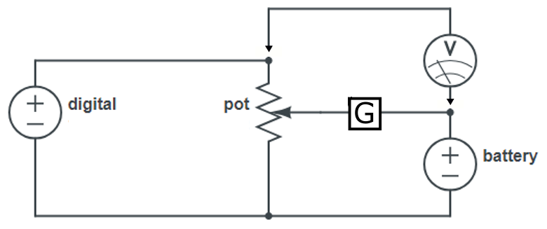
Figure 7: A circuit balanced by the resistance value of the potentiometer. When the galvanometer reads zero current, the volage on each side of the circuit is balanced.
- Build the circuit shown in Figure 7. Note that you are using TWO voltage supplies here; oriented such that their poles are aligned. Note that the galvanometer has to be in series in your circuit since it is basically an ammeter. Put the battery into its holder if it isn’t already in there.
- Plug the output of the PASCO digital supply into the circuit component with the red and black cable jacks. Set the output to 3 V. Your galvanometer will likely be off scale at this point.
- Adjust the potentiometer until the galvanometer reads zero current – or at least very close to zero. It’s hard to get the needle exactly to zero since we’re measuring microamps, which is an incredibly small amount of current to measure.
- Measure the voltage of the voltage-divider output when the circuit is balanced. Remember that the voltage across the entire potentiometer is not interesting or useful.
- Disconnect the battery terminal and measure the battery voltage directly. Compare your results.
4.3 Wheatstone Bridge

Figure 8: A simple voltage divider.
- Build the circuit shown in Figure 8. Make sure you recognize where the four resistances of the Wheatstone bridge are, and that the galvanometer goes between the two pairs.
- Set the voltage from the computerized PASCO software to 1.5 V. You should see the lightbulb glow dimly.
- Use the potentiometer to balance the two sides of the circuit. The galvanometer should read close to 0 uA.
- Turn the digital DC voltage to zero, disconnect the potentiometer, and measure its resistances. You don’t have to remove the potentiometer unit, just remove connections to it. Use your measurements to solve for the unkown resistance value of the hot bulb.
- Reconnect the potentiometer and set the computerized DC source to three other values between 1 and 4 V.
- Plot your resistance measurements as a function of voltage from the digital DC source. How does the resistance of the bulb change and what does that tell you about resistance vs temperature?
4.4 Kirchhoff’s Law
- Don’t change your circuit! It should have three loops in it (consider the galvanometer as a zero-resistance wire).
- Show that the sum of voltages in each loop is zero, as claimed by Kirchhoff’s 2
 law. Use the wireless voltmeter to make any measurements that you need to make.