Lab 1: Simple Circuits
Procedure
4.1 Setting Up
- Build the circuit shown in Figure 6(a). Make sure the switch is OPEN and the battery is OUT of the circuit.
- Use the CAPSTONE software to monitor the current and voltage in the circuit. Hopefully both are zero since the circuit isn’t powered, yet.
- Insert the battery and CLOSE the switch. Do your results make sense for a 3 V power supply?
a) 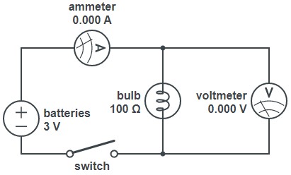
b) 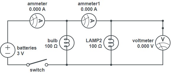
c) 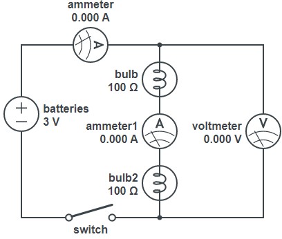
Figure 6: Simple circuits in series and in parallel. Note that you only have one ammeter, so you’ll have to move it around. Ignore the values of resistance for the bulb; those are just the default values in CircuitLab.
4.2 Series & Parallel Circuits
ALWAYS OPEN THE SWITCH AND TAKE THE BATTERY OUT OF THE CIRCUIT WHEN MAKING CHANGES!
- Put two lamps in parallel, as in Figure 6(b). Measure the voltage across the lamps. Measure the current before each lamp. How bright are the lamps compared to when there was just one?
- Put the two lamps in series, as in Figure 6(c). Measure the voltage across the lamps and across each lamp individually. Measure the current before each lamp. How bright are the lamps compared to when there was just one?
4.3 Charging a Capacitor
- Build the circuit shown in Figure 7. Note that the resistor and capacitor are in parallel.
- Use the CAPSTONE software to make a table of time and voltage measurements. The switch should still be OPEN, so you should definitely be seeing 0 V.
- CLOSE the switch and the batteries will charge the capacitor. The voltmeter should be reading the full voltage of the batteries: 3 V.
- OPEN the switch! The charged capacitor will slowly discharge through the resistor and the measured voltage should decrease EXPONENTIALLY. You should have a voltage measurement every second of this discharge. If you don’t just charge the capacitor again. It takes like 2 seconds.
- Save the data to a notepad file and email it to yourself or save it with a USB stick. or just write it down; it’s like 10 pairs of numbers.
- Repeat these measurements for a couple values of resistance. The calculated time constant should be increasing with increasing values of resistance.
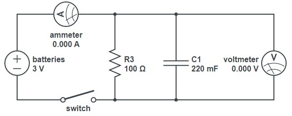
Figure 7: RC circuit.