Lab 3: RC Circuits and Oscilloscopes
Prelab Submission
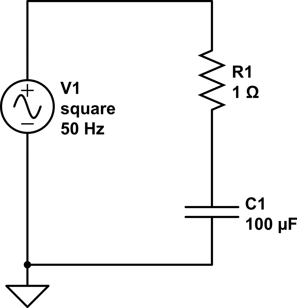
Figure 7: Simple RC circuit that you will make in Circuitlab. Measure the voltage between the resistor and capacitor.
- Use Circuitlab to make the circuit shown in Figure 7. Note the 50 Hz square wave as the voltage source.
- Once your build works, you can simulate the circuit in real time! Open the ‘Time Domain’ menu and use the settings shown in Figure 8. Note that the voltage measurement is coming from between the resistor and capacitor. Use time-domain settings such that you can see several wavelengths of the 50 Hz square wave. Make sure the size of your time step is much smaller than your wavelength!
- Run the simulation using
 values of 1, 10, and 100 Ohms.
Submit a screenshot of the resulting plot of each simulation and comment on any general trends that you notice.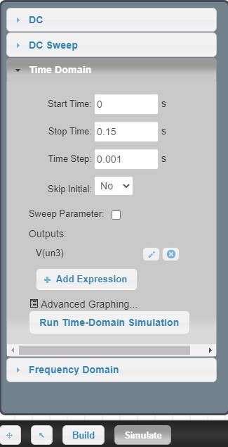
Figure 8: CircuitLab controls for simulating circuits in real time. Set the start and stop times and the size of the time step: ((stop time)-(start time))/(time step) = number of points on your plot. Then choose points in the circuit where you would like to measure the voltage; they will show up as ‘Outputs’. Then click ‘Run Time-Domain Simulation’.