Lab 4: RL Circuits and Filters
Prelab Assignment
- Use Circuitlab to build the circuit shown in Figure 6.
- Run the frequency-domain simulation from 1 kHz to 100 MHz using 5 points/decade. Measure the voltage across the resistor.
- Save a screenshot of your resulting plot.
- At what frequency is the amplitude of the wave a maximum? What is the approximate range of frequencies where the amplitude stays above -3 dBV?
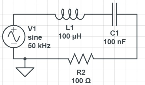 Figure 6: An RLC circuit to simulate in Circuitlab. Measure the voltage output across the resistor.